
Tuning Tracing
Users can control tuning tracing procedure using the Conversion Options dialog box.
Tuning is performed in the Options and Trace tabs of the Conversion Options dialog box. Tracing is also influenced by parameters of the Separate and Symbols tabs, which are described in the section “Setting up Symbol Recognition Options” on page 198.
To setup tracing parameters
1. Choose Conversion Options form Convert menu or click the button  on the Raster to Vector toolbar
2. Choose Options tab.
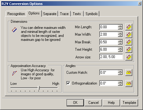
The Options tab of Conversion Options dialog.
3. Specify the new parameters by entering values or measuring with a ruler on the image, and then click OK.
Tracing Parameters Description
The Options tab
| Parameter | Description |
|---|---|
| Min Length | This parameter defines the minimum size of a raster object that can be recognized. |
| Max Width | This parameter defines the maximum width of raster lines that can be approximated by lines, arcs, circles, and polylines. If the width of a raster line exceeds Max Width, then the only possible mode is Auto tracing and approximating with an outline object. |
| Max Break | Sets the length of the maximum ignored breaking raster lines. If a raster line is broken into parts it should be traced as an entire object, then the value of Max break should be set to the largest gap between the raster line parts. The program will ignore the breaks and create single vector object, approximating the whole raster line. By setting a comparatively large value of the parameter, users can, for example, trace dash-dotted raster lines, and arcs as single entities.Enter the values of Min Length, Max width and Max break from the keyboard or measure them on the screen. |
| Approximation Accuracy | This parameter determines the accuracy of approximation of the original raster object with a vector one. If the original image is distorted (,For example, circles have the form of ellipses.), then reduce the value of the Approximation Accuracy parameter. However, this leads to inaccuracies in recognition, for example the program might take a short arc for a line. When the quality of a raster image is high, increase the value of the Approximation Accuracy parameter. Sometimes before tracing the quality of the raster image can be improved by application of a smoothing filter. |
| Custom Hatch | This parameter defines an angle of raster lines which will be recognized as hatch during tracing. |
| Orthogonalization | If this option is on, then the tracing in Auto and Line modes aligns created segments either perpendicular to or parallel with the base direction if the deviation of the original object from these directions is insignificant. The base direction is set in Base angle. The accepted deviation is determined automatically by the Approximation Accuracy parameter value. Enter an angle specifying the base direction of orthogonalization. - or – Click the button at the box name and specify two points on the image. The angle value between the line connecting these points and the axis X will be shown in the Base angle. |
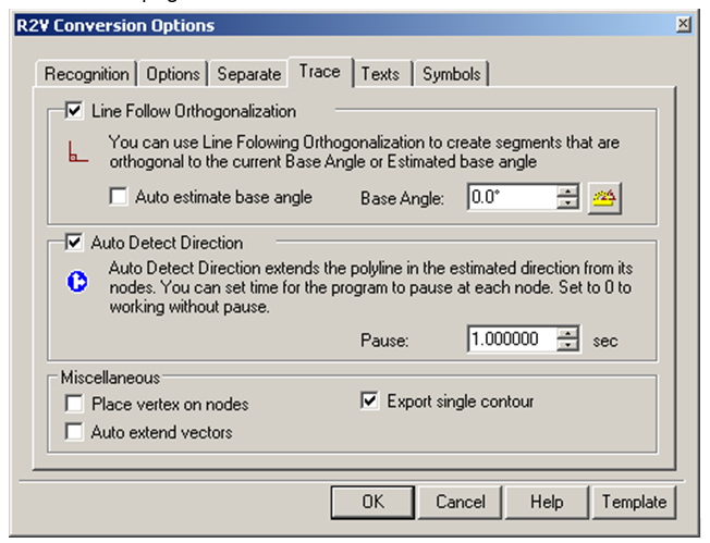
Trace Tab
This tab represents parameters controlling the procedure of tracing polylines, described on page 167.
| Parameter | Description |
|---|---|
| Line Follow Orthogonalization | If this option is on, then the line following tracing automatically aligns segments of created polylines perpendicular to each other. Segments become either perpendicular or parallel with the base angle; if they are not too skewed from the main direction. The base angle is set in the Base angle box of the Options tab. If the Auto checkbox is on, then the program automatically defines the base angle by the direction of the polylines longest segment. The Approximation Accuracy setting in the Options tab controls the maximum angle of deviation that segments can have in relation to the Base angle and still fall under orthogonalization.Use this option when tracing raster objects consisting of perpendicular segments, for example when tracing buildings on plans. |
| Auto estimate base angle | Sets the mode which automatically defines the base direction of polyline segments orthogonalization. The base angle for each traced polyline is defined separately. |
| Base Angle | Enter an angle specifying the base direction of orthogonalization. - or – Click the button at the box name and specify two points on the image. The angle value between the line connecting these points and the axis X will be shown in the Base angle. Setting on Auto estimate base angle has priority over this option. |
| Auto Detect Direction | Sets the mechanism by which the program will automatically define the direction of tracing. After the program reaches a node, it tries to find the following raster line part, which is an extension of the traced object. |
| Pause | Sets a period in seconds, during which a segment to extent tracing should be chosen when the Auto Detect Direction mode of tracing is on. Unless the user manually specifies another extension during this time interval, the program will continue tracing in the automatically selected direction. Setting Pause to 0 disables this option. |
| Place vertex on nodes | When this checkbox is on, the program when tracing polylines inserts vertices at intersections of a generated vector polyline with raster objects (nodes). |
| Auto Extend vectors | This feature simplifies forced selection and tracing of arcs and lines. While recognizing a line, click two arbitrary points on it and WiseImage automatically extends the resulting line to its endpoints. While recognizing an arc you can click three arbitrary points on it; and WiseImage automatically extends the resulting arc to its endpoints. |
| Export single contour | This checkbox tunes the performance of outline tracing (see page 166). If the checkmark is present, then tracing creates the outer contour of the object. If the checkmark is absent, then tracing yields the outer contour and the inner one, if there are “holes” in the raster object. |
Feedback
Copyright © 2026 CSoft AS
—
Powered by 
Post your comment on this topic.