
Tuning Selection
Tuning selection is performed in the Options tab of the Conversion Options dialog box. The user can control the raster object selection methods, based on Object Recognition and Line Following algorithms.
To set raster selection parameters

1. Click the Conversion Options button on the Raster to Vector toolbar.
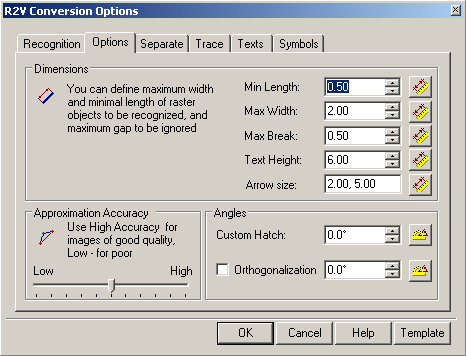
2. Shift to the Options tab.
3. Specify new parameters, and then click OK.
Raster Selection Parameters
Raster selection is only affected by three parameters in the Options tab: Max Width, Max Break and Approximation Accuracy.
| Max Width | Defines the maximum width of raster objects that can be selected with the methods based on Object Type Recognition and Line Following. The program does not select lines with widths larger than the specified value. |
| Max Break | Defines the length of the largest break to be ignored in a raster line. If raster line breaks are less than the specified value, then when selecting the line breaks will be eliminated and the line will be chosen as an entire raster object. |
| Approximation Accuracy | When selecting raster, using the methods based on the Object Type Recognition, Approximation Accuracy defines the accepted deviation of raster object symbols from their vector prototypes. If the original raster lines are distorted (for instance, raster circles are elliptical), then selection accuracy can be improved by moving the Approximation Accuracy slider to the left (Low). If the original raster image is of a good quality, then move the slider to the right (High). |
Forced selection is also influenced by Auto Extend Vectors mode, which is toggled in Trace tab of Conversion Options dialog (see Tuning Tracing).
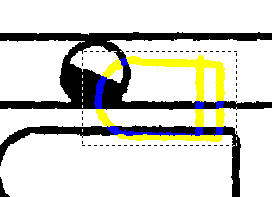
The Max Width and Max Break values can be measured on a raster image.
To measure Max Width on an image
1. Click the button at Max Width.
2. Specify two points in the raster image so that the line connecting these points crosses the thickest part of the raster line.
The program defines the Max Width value equal to the length of the line part that covers the raster object.
To measure the Max Break on an image
1. Click the button at Max Break.
2. Specify two points in the raster image so that the line connecting these points crosses the largest break in the raster line.
The program defines the Max Break value equal to the length of the line part that covers the raster background.
Raster Selection Transparency
Raster selection on monochrome images can be switched to semi-transparent mode for convenience. This is often done for operations requiring a higher precision.
See Colours > Raster Selection > Semitransparent checkbox in Preferences dialog.
Post your comment on this topic.