
Line Style management
Every WiseImage vector object has a line style associated with it (see Line Type property in the Inspector). The line style is a definition that determines a visual representation of lines of drawing entity. It includes particular dash-gap-marker sequence, the relative lengths of dashes and gaps, styles combination and etc. Any of the standard line styles provided by WiseImage can be used, or new line styles can be created and combined.
A wide spectrum of line types can be created:
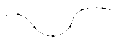
Line style that uses arrow markers
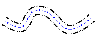
Combined line style
All standard WiseImage line styles cannot be deleted or renamed, however they can be freely modified.
To set line type
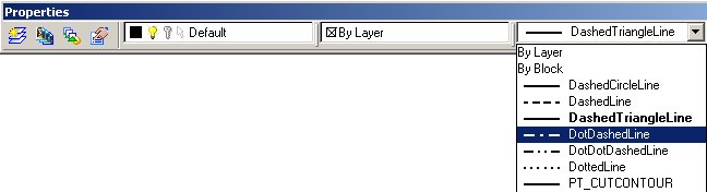
You can set line type on the Properties toolbar or in the Inspector window.
The Line Style Manager
It’s used to create, delete, modify and combine line styles.
To start Line Style Manager  , click the Style from the Tools menu.
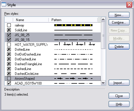
The Pen Styles list box shows all line styles in the document. It supports multiply selection (with SHIFT or CTRL keys), and drag and drop capability.
| Locked field | Mark desired line styles with a ( ) sign to make them available in the drawing (in the Inspector dialog and Properties toolbar). ) sign to make them available in the drawing (in the Inspector dialog and Properties toolbar).WiseImage has a number of standard line styles, which can be modified but not renamed or deleted. These line styles are marked with a (  ) sign shown in this field. ) sign shown in this field.All marked ( ) line styles are placed inside saved CWS. Thus they can be distributed with a document |
| Name field | Displays a line style name. |
| Pattern field | Shows a line style visual representation. |
| Description | Shows full information about a selected line style: name, number of pattern pairs, interval pairs separated by comma. |
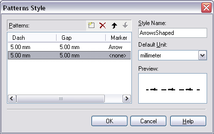
| New button | Shows the Pattern Style dialog to create a new line style. |
| Combine button | Shows the Combined Style dialog with included selected line style to create a new combined line style. If line style was not selected or selected style was already combined one, then this button shows empty Combined Style dialog. |
| New Copy button | Shows the Pattern Style dialog window filled with parameters of selected line style to create a copy of this line style. The line style name for the new line style by default is: “Copy of CopiedLineStyleName”, where the CopiedLineStyleName is the name of a copied line style. If selected style is a combined one, then this button shows Combined Style dialog. |
| Modify button | Shows the Pattern Style dialog to modify a selected line style. If selected style is a combined one, then this button shows Combined Style dialog. All standard WiseImage line styles, are marked with the key symbol and cannot be deleted or renamed, but can be freely modified. |
| Delete button | Deletes selected line style(s). All standard WiseImage line styles, are marked with the key symbol and cannot be deleted or renamed, but can be freely modified. Be careful not to delete a line style that is used by some document objects. If a line style used is removed, then after the document is reopened, the name of this deleted style will be displayed in angle brackets for all objects that use this style, but actually these objects will be displayed in a solid line style. |
| Import button | Import line style(s) from the AutoCAD line type definition file (.LIN file). A LIN file can contain definitions of many simple and complex line styles. This file has an ASCII format. Select desired line styles in the Line type import dialog that appears: 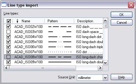 WiseImage converts shapes and text symbols into markers during line style import: 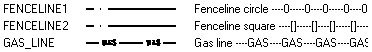 You can also ignore such line styles: 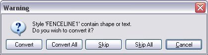 |
| Close button | Closes the Line Style Manager dialog. |
The Pattern Style dialog
This dialog is called from the Line Style Manager and used for creation, modifying and copying line styles.
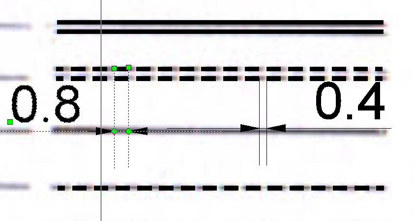
The format of the line style definition includes a number of patterns consisting of three parts: Dash part length value – Gap part length value – Marker (optionally)
The Marker – is the same marker that is stored in .MRK file and used to place at the entity ends.
It is placed in the middle of the Gap of a current pattern. The user can assign various markers to different patterns of the modified line style.
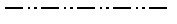
For example, a standard WiseImage line style, called DotDotDashedLine, includes three patterns defined as:
Dash Gap Marker
8mm 2mm
1mm 2mm
1mm 2mm
This indicates a repeating pattern starting with a dash 8mm long, a gap 2mm long, a dot, a gap 2mm long, a dot and another gap 2mm long. This pattern continues for the length of the line. The line style would be displayed as shown below:
To create a new line style
Press the New button in the Style dialog:
Set the style name and select measurement units from the Default unit combo-box.
Press the  New Item button, enter one by one the size of dash and gap. Specify marker. Observe the process in the Preview field.
Edit elements with the buttons  Delete Item and
  Move Item Up / Down.
Press OK.
To modify an existing line style
From the Style dialog pane choose a style to modify.
Press the Modify button, and then make necessary changes (see 2, 3 of the previous section).
Press OK. The style name will remain the same.
To create a new line style on the base of an existing one
Choose a line style from the Style dialog.
Press the New Copy button, make necessary changes.
Enter the name in Style Name the field.
Press OK.
Pattern Style dialog buttons and controls
The  button button |
Creates another pattern. |
The  button button |
Deletes a selected pattern from the list |
The  buttons buttons |
Moves patterns up and down along the list. The upper patterns are drawn before the lower patterns in the line style. |
| Dash field | Specify the length of the dash part of the pattern. |
| Gap field | Specify the length of the gap part of the pattern. |
| Marker field | Specify the Marker that will be placed in the middle of the gap of a current pattern. Various markers can be assigned to different patterns of a modified line style. |
| Style name | Represents a line style name. A line style belonging to WiseImage standard line styles cannot be modified. |
| Default Unit | Specifies the measurement units for dashed and spaced parts length of the line type. |
The Combined styles
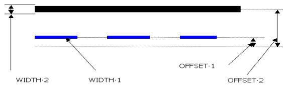
A combined line style consists of several simple ones. An offset, line width and colour can be specified for each included style.
The Offset sets a displacement value of a line relative to the central axis of a combined style. Positive values mean displacement to the right, negative – to the left. The lines with the same Offset value will be placed one over another.
The Line Width sets a width value for a specified style.
By default, the line color corresponds to the color of the included style, it can be changed though.
Using combined styles makes it possible to create line styles that can virtually represent any kind of an entity in a drawing such as a state border, railroad and more.
To create combined style
A Combined style can be created using a set of simple (not combined before) line styles. This can be done in the Combined Style sub-dialog.
Select all simple line styles which you need to combine in the Line Style dialog and click the Combine button to create a new combined style.
The Combined Style sub-dialog with all the preselected styles included will appears.
There you can edit Offset, Width and Color parameters for each combined style.
To add a new style to a set or include an instance of an existing one, use the  New item button. Click the
  Delete item button to delete any style. Use the
  buttons to change an item order in the set. The Style Name box specifies the name of a combined style and the Default Unit box specifies the measurement units for the Offset and Width parameters.
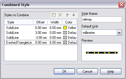
Example: Creation of a railway line style
To create a railway line style follow the steps:
Open the Line Style dialog.
Choose the native WiseImage SolidLine and DashedTriangleLine styles in the list by selecting them with the Ctrl button pressed.
Click the Combine button.
In the appeared Combined Style dialog type the “railway” style name and specify millimetres as default units.
Click the  New item button twice to add two style items to the list. Click on the Style field of every newly added item and choose the SolidLine style name. Now there are three instances of the SolidLine style and one instance of the DashedTriangleLine style in the list.
 This set represents a thin solid line.
Set a width value equal to 6mm and yellow color for the first SolidLine style instance.
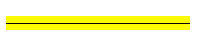 A wide yellow line appears.
Set an offset value equal to 3mm for the second SolidLine style instance
and an offset value equal to – 3mm for the third one.
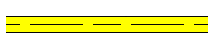 Now we have a wide yellow line with a thin black DashedTriangleLine in the middle bounded with two thin black solid lines. Set a width value for DashedTriangleLine equal to 6mm.
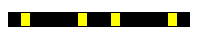 The line of yellow color and the line of DashedTriangleLine style have the same width and offset values so they are imposed one over another.
Post your comment on this topic.