
Elevations arranging
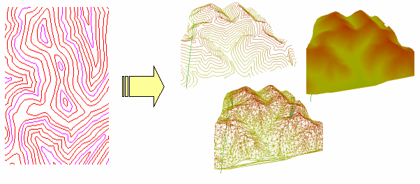
The Arrange Elevation command assigns the Elevation property to polylines with a specified step. It is used to assign elevation values for vectorized contour lines on topographical maps. When working with vector data in AutoCAD, the Elevation property for 2D-polylines is used as the Z-coordinate. Open the 3D View window during arranging elevations to see all changes in 3D projection.
To perform the Arrange Elevation
If polylines are selected before running the command, the command will be only applied to these objects.
Start the Arrange Elevation command: click the Arrange Elevation from the Correct menu or click the  button on the Vector Correction toolbar.
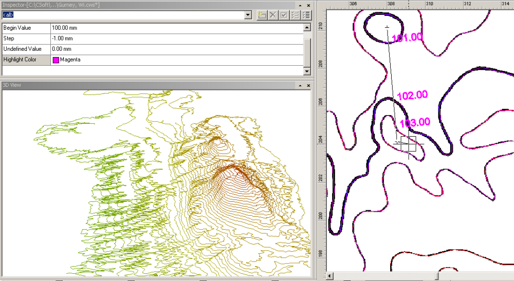
Set a Begin Value and a Step in Inspector. Elevations are assigned starting from the first object to the last one. If a step has a negative value, the elevation will go down from the start value.
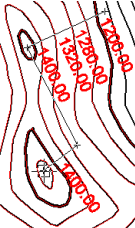
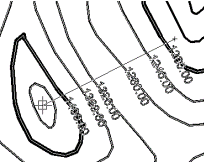 Draw a rubber line so that it will intersect the polylines to be assigned elevations. Thus, the order of intersecting objects is important – the first object will be assigned the value entered in the Begin Value property. The other objects will be assigned the values depending on the order and the Step parameter.
Dynamically calculated elevation values for every intersected polyline will be seen on the screen.

 Calculate an elevation that will be assigned to an object according to this simple formula: Resulting value = Begin Value +/- order * Step. For example, 1000 (starting value) + 100 (step) * 5 (order) = 1500
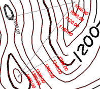 The Begin Value and the Step properties are needed only for the first polylines intersection step. The command automatically calculates the elevation of the newly specified polylines basing on the elevation of the polylines whose elevation value has been specified. These polylines are highlighted with a colour specified in the Highlight Colour property of the Inspector. There is no need to recalculate and re-enter Begin Value and Steep for every new logical group of isolines – they are calculated automatically.
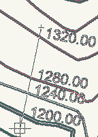 If the first polyline intersected with a rubber line has been processed, then the command uses its Elevation value as the Begin Value. If two or more polylines with assigned elevations have been intersected at the beginning, then the command automatically calculates the Step parameter too.
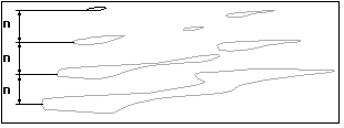
 When working with Arrange Elevations only intersect polylines whose elevations are either increasing or decreasing, but not both together. Use two or more steps to process all polylines.
To distinguish polylines with assigned Elevation values from polylines with unassigned Elevation values this command uses the Undefined Value property of the Inspector. It is equal to zero by default. The Undefined Value specifies a single Elevation value which will mean an unassigned elevation. All other elevation values mean assigned elevations. For example:
Change the Undefined Value parameter specified as an unassigned elevation value to an assigned one. For example, the drawing has a ground (zero) elevation value is an assigned value. Then just set Undefined Value to any other (–30 for example).
3D View
This window shows a drawing in 3D projection where the Z coordinates represent elevation values. Zoom, pan and rotate a drawing in this view using the mouse and/or buttons. It is useful for viewing vector topographic maps.
Various view projections and surface view styles can be specified.
Open the 3D View window during Arrange Elevation to trace errors as all document changes are dynamically reflected in this view.
The 3D view window does not show polylines whose elevations are equal to the Unsigned elevation value during the Arrange Elevation command execution.
3D View buttons and controls:
| Rotate | Use 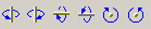 buttons to rotate the window content. Rotate a 3D drawing using the mouse to drag the 3D drawing in any direction. buttons to rotate the window content. Rotate a 3D drawing using the mouse to drag the 3D drawing in any direction. |
| Zoom | Use  buttons to zoom in, out and zoom all. This can also be implemented by scrolling the mouse wheel. buttons to zoom in, out and zoom all. This can also be implemented by scrolling the mouse wheel. |
| Pan | Use the third (middle) mouse button for panning. |
| View | Use  button to change the view. Isometric, Front, Backward, Right, Left, Top, or Bottom can be set. button to change the view. Isometric, Front, Backward, Right, Left, Top, or Bottom can be set. |
| Perspective | Use  button to change 3D perspective. The perspective slider works like a zoom slider on a camera – it changes perspective and zoom distance simultaneously. To change zoom only use the zoom buttons. Switch on the Ortho checkbox to set orthogonal projection. button to change 3D perspective. The perspective slider works like a zoom slider on a camera – it changes perspective and zoom distance simultaneously. To change zoom only use the zoom buttons. Switch on the Ortho checkbox to set orthogonal projection. |
| Surface Type | Use the  button to change 3D surface type. button to change 3D surface type.It can be represented by Isolines, Triangles or Surface. |
To open 3D View window choose Show 3D View from the View menu.
Post your comment on this topic.