
Binarization and Colour Separation
This section describes the procedures of converting colour and greyscale images to monochrome raster images (raster layers).
The original image is a raster file, obtained after colour or greyscale scanning. Binarization creates monochrome raster images, containing black-and-white representations of colour objects. For example, from one image of a scanned map it is possible to extract and place objects of different colours (e.g. isolines, roads, rivers, and other objects) to separate monochrome layers.
Another method to obtain a monochrome image from a colour one is colour separation. WiseImage can convert a colour image to a set of monochrome raster layers. This method guarantees that the black-and-white (or monochrome) representation of each pixel of the original image will be placed on a certain layer.
Vectorization or tracing can further convert the resulting monochrome images to vectors. Vectorization of a layered raster image is considerably more effective than vectorization of a raster obtained by scanning of colour originals.
Running Binarization
Binarization creates a new monochrome image of a specified colour, which is placed on the specified layer. Using the specific criterion the program defines which pixels of the original (colour or greyscale) image should become black (foreground pixels), and which ones should become white (background pixels), and then generates a monochrome image and places it on a new raster layer. The criterion for division of pixels into two sets is defined by the selected binarization method and its parameters (threshold values or a set of colour range). The selection of pixels is ruled by the settings, specified in the Binarization dialog box. A new monochrome image is named _N; N is an integer.
This operation can be applied to several images at once. If no images are selected, then the command will be applied to all images (that are visible and located on unlocked layers). If several images are selected, then the command will be applied to those that are visible and located on unlocked layers.
Binarization is applicable for images with clipping boundary. Using this feature, users can restrict the binarization area on any image.
For information on clipping boundary application see Cropping .
To binarize an image
1. Choose the images to process (visible, on unlocked layers). Otherwise, the command will be applied to all appropriate images.
2. Click the  button on the Image toolbar or choose Binarization from the Image menu.
3 In the dialog window select a method and adjust its parameters.
4. Click Apply.
Binarization creates a monochrome image from a colour raster image.
Binarization methods
To convert colour and greyscale images to monochrome ones, various conversion algorithms are used, which are called binarization methods. It is recommended to choose a conversion method appropriate to the image type.
Threshold by Grey
Threshold by Grey converts colour pixels with a brightness values above the specified level to background dots, and pixels below this level to image dots.
This method may be used for converting both colour and greyscale images. When converting a greyscale image, WiseImage uses its grey levels. When converting a colour image, the grey levels are defined by the brightness value of colour dot.
Threshold by RGB
When using Threshold by RGB, define three threshold levels for the Red, Green, and Blue components. WiseImage converts colour dots with Red, Green and Blue values below the appropriate threshold levels to black dots (image dots) of the monochrome image.
Range by Grey
Range by Grey allows conversion of colour pixels, with any brightness value, to image dots. Using this method, first specify a number of basic levels of grey. These levels are used as midpoints for ranges. For each of the specified levels, define a range half-length. A range half-length is a number of grey levels below and above the specified grey level.
Range by Grey converts pixels that have grey values within all specified ranges to foreground dots. Other pixels are converted to background dots.
This method may also be used for converting colour and greyscale images. Grey levels for colour dots are calculated as described in Threshold by Grey.
Range by RGB
This method can convert colour pixels of the specified RGB ranges to image dots.
To specify an RGB range, first select a central range colour. The Red, Green, and Blue components of this colour define the position of the RGB range central point. For each of the colour components (R, G, and B) specify the appropriate range half-lengths. The range half-length for R, G, or B component is a number of R, G, or B levels below and above the selected R, G, or B level. For example, if the R level of the selected colour is equal to 50 and its range half-length for R component is equal to 10, then the RGB range includes colours with the R components from 40 to 60.
Range by HSV
This method allows the conversion of pixels of analogous colours to image dots. Analogous colours are closely related colours in the human perception of colour, e.g. red orange, dark green light green, etc.
To convert an image using Range by HSV, specify one or more HSV ranges. The HSV range is defined by a selected colour and H, S, V range half-lengths. The HSV range is similar in design to the RGB range described above. Note that Hue is expressed as an angle between 0° and 360°, Saturation and Value are measured as a percentage from 0 to 100.
Using this method for converting greyscale images provides a low-quality result.
Binarization dialog box
To open the Binarization dialog box
Choose Binarization from the Image menu or click the  button on the Image toolbar.
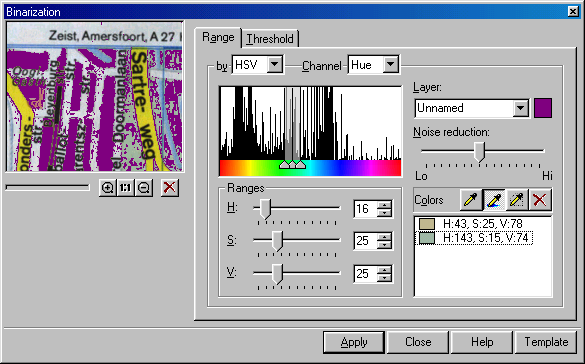
The Binarization dialog with the Range tab open
The controls and buttons described below are the same of the Threshold and Ranges tabs of the Binarization dialog box.
Preview window
This window dynamically displays the binarization results of an image part. Note that if a colour sample in the image is chosen with an eyedropper, the preview window marks the position of a selected pixel with a cross. This only happens if colour selection is performed in the preview area, the position of which is shown with a coloured frame (red by default) on the image.
For more information on Preview window and Preview Area toolbar see Preview window.
Noise Reduction
This slide sets the sensitivity of the binarization tool to small details in the image. If the maximum level of noise reduction is set, then the quantity of raster noise and holes in the obtained monochrome raster objects is reduced. However, the high level of noise reduction decreases the binarization quality of small and thin details, such as texts, thin lines, etc, since small details can be taken for noise. If a low level of noise reduction is applied, then the quality of small detail binarization improves, but the quantity of raster noise increases.
By
Depending on the chosen tab, this list allows users to select a binarization method. For example, if the Range tab is chosen, the choice is Range by Grey, Range by RGB or Range by HSV.
Channel
A colour information channel type can be chosen from this list. The term colour information channels stands for the information on the colour components of the image pixels by a certain colour representation model.
The number of available channels depends on the image type. Every colour image has five channels: Red to store information on the red colour, Green to store information on the green colour, Blue to store information on the blue colour, Hue to store information on hue, and Grey to store information on the grey colour components (brightness) for each colour. For greyscale images the Grey channel is used only.
Channel histogram window
The histogram of the selected channel is displayed in the Channel list. Histogram is a graphic representation of a colour component value distribution by image pixels, defined by a selected channel. A component value is measured along the histogram horizontal axis (low values are on the left, high values are on the right). Along the vertical axis are placed a normalized number of pixels with the specified colour component value. Thus, the histogram extremes correspond to the most frequent component values, and the minimums correspond to the least frequent values.
Depending on a selected binarization method, either one or three triangular sliders can appear in the bottom histogram part. These sliders allow the adjustment parameters of the current binarization method, i.e. to specify range parameters and threshold level value.
Layer
Allows the specification of a layer name, on which a monochrome image will be placed after binarization, and a raster image colour.
Apply
Starts the binarization procedure.
Template
Used to store and load all the parameters for all binarization methods.
Dialog box tabs
There are two tabs in the Binarization dialog box: Range and Threshold. The first one is used to specify the binarization range methods parameters; the second is used to specify threshold methods parameters.
Range tab
This is applied to tune the following range methods: Range by Grey, Range by RGB or Range by HSV.
Colours
This list shows information on central colours of specified ranges and allows to selection of a range for correction and deletion. The left part of the list shows a sample of a selected colour (or grey tone), and the right part shows colour component values in the current colour model (grey level for greyscale images). To select a range, click its appropriate colour in the Colours list.
Above there are three buttons with eyedropper pictograms, these allow the creation of new ranges.
 Colour selection allows the creation of a new range by selecting a colour in the image.
WiseImage creates a new range, using the colour of the specified pixel as the range central colour.
 Averaged colour selection allows the creation of a new range by choosing an averaged colour in the area around the pixel clicked.
WiseImage calculates the average colour value in the area of the specified pixel and creates a new range, using the calculated colour as the range central colour. The half-lengths of the created range are automatically adjusted to take close colours, found in the specified pixel area.
 Area averaged colour selection allows the creation of a new image by calculating the averaged colour of an arbitrary area in the image.
Click the button and specify vertices of a polygonal area or drag the cursor, outlining the boundary of the image polygonal area. Complete the selection of the area with a double-click. WiseImage calculates the average colour value in the specified area and creates a new range, using the calculated colour as the range central colour. The half-lengths of the created range are automatically adjusted to close colours, found in the specified pixel area.
Area averaged colour selection allows the creation of a new image by calculating the averaged colour of an arbitrary area in the image.
Click the button and specify vertices of a polygonal area or drag the cursor, outlining the boundary of the image polygonal area. Complete the selection of the area with a double-click. WiseImage calculates the average colour value in the specified area and creates a new range, using the calculated colour as the range central colour. The half-lengths of the created range are automatically adjusted to close colours, found in the specified pixel area.
Ranges
Use this box to change the half-lengths of a range, selected from the Colours list. The type, name and a number of sliders and boxes depend on the current conversion method. For example, when choosing Range by HSV, the following sliders and boxes to modify the range half-lengths are displayed: hue– H, saturation – S and brightness – V.
When Range by Grey is chosen, there is only one slider and one box to enter the half-length of brightness range.
Sliders of channel histograms
This tab has three triangular sliders on the histogram channels corresponding to the selected binarization method. These sliders allow changes to the central colour components (grey central level) and the half-length of the range selected from the Colours list.
When Range by HSV is chosen, the sliders at the channel Hue histogram appear, the selection of Range by RGB causes the appearance of sliders at the Red, Green and Blue histograms. When Range by Grey is chosen, the sliders appear at the histogram of the Grey channel.
Threshold tab
This is used for binarization with Threshold by Grey or Threshold by RGB.
Threshold
This command displays the specified algorithmic threshold values of the current method of threshold binarization. To modify a value, move the corresponding slider.
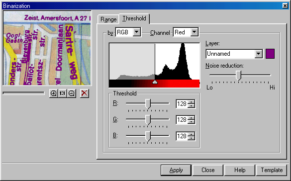
 Threshold tab of the Binarization dialog
Sliders of channel histograms
One triangular slider appears on the channels histogram corresponding to a certain binarization method. This slider allows the modification of the threshold value of a colour component or grey level.
When Threshold by HSV is chosen, the sliders appear at the Red, Green and Blue histograms. When Range by Grey is chosen , the slider only appears at the histogram of the Grey channel.
Tuning Binarization
To fine-tune the binarization procedure, choose an appropriate method. The selected method type defines a customizing method. For each of two threshold methods specify one or three threshold values at the histogram. Also specify a set of ranges of the corresponding types that contain the extracted colours.
For any method specify a layer to place an image, obtained after binarization.
To tune threshold binarization
1. Choose the Threshold tab from the Binarization dialog box.
2. From the By list choose an appropriate method.
3. Tune the threshold values for the selected method.
When tuning, use the preview window of the Binarization dialog box to observe the results of parameters’ modification. Note that an image preview at the scale 1:1 provides the most reliable results. For more information on preview tools see Preview window.

Binarization dialog with Threshold by Grey
If the Threshold by Grey method is selected, then choose Grey in the Channel list to see the grey level histogram. Specify a threshold value with triangular or G sliders.
If the Threshold by RGB method is selected, then adjust the R, G, B threshold values. For this purpose the sliders on histograms of Red, Green, and Blue channels can be used.
4. Use the Noise Reduction slider to adjust noise reduction and improve binarization quality.
By default this parameter is specified as an average value. If binarizing large filled areas, then decrease this parameter value (close to Lo mark) to reduce the quantity of raster speckles and non-filled holes when binarizing objects.
When trying to get a monochrome layer containing images of small or thin objects (texts, characters, isolines, or grid), increase this parameter value to prevent these small objects, caused by noise reduction, from being thinned and distorted. This will increase the noise level of the obtained object.
5. Define a monochrome image colour and a name of the layer to place the binarization results on.
Enter a name in Layer. To define a colour, click on a colour pattern and choose a colour from the box, click OK.
To tune the binarization using the range method
1. From the Binarization dialog box, choose Range.
2. From the By list, choose a required type of range method.
Set the parameters of the chosen method.
When tuning use the preview window of the Binarization dialog box to observe the result of changing parameters. Note that the most reliable results are obtained on viewing the image at a scale of 1:1. For more information on preview tools see Preview window.
3. Specify a set of ranges capturing the colours (grey levels) of the colour image objects to be moved to a separate monochrome level.
To do so, create a required number of ranges, using the eyedropper buttons and control the result of adding each range in the preview window. If the range addition results with unwanted image pixels being captured, then try to modify the range parameters using the Ranges box or the channel histogram sliders. If an acceptable result cannot obtain for a range, then delete it using the Remove Colours button.
Note that during selection of a colour pattern on the image with the eyedropper, when selecting a colour in the image preview area, the position of the chosen pixel is marked with a cross in the preview window. It enables a pixel lacking colour to be chosen.
To add a range
Click  or
or  buttons and point on the image a pixel to binarize.
- or -
Click  button and choose an area on the object to binarize.
An element related to the created range appears in the Colours list.
To change the created range parameters
Use sliders and boxes of Ranges, or channel histogram sliders.
To delete a range
Click an element corresponding to the range to be deleted in the Colours list, press the Remove Colour  button.
Binarization example
When performing the instructions below control the binarization procedure through the zoom buttons, preview window and with the buttons on the Preview Area toolbar:  ,
,  , and
, and  . For more information on preview tools see page 34.
Image loading
1. Choose Open from the File menu.
2. In the displayed dialog open the SAMPLES folder and open the MAP.TIF file.
Binarization
 Open the Binarization dialog box.
Click Binarization on the Image toolbar or choose Binarization from the Image menu.
Open the Binarization dialog box.
Click Binarization on the Image toolbar or choose Binarization from the Image menu.
When the dialog opens, the preview window displays the central part of the image at a scale of 1:1.
The position of the preview area is indicated with a red frame in the image.
 Change the position of the preview area using the Preview Area buttons. (The Preview Area toolbar is shown automatically after the Binarization dialog box is opened).
Unless parameters of Binarization not specified, the original image is displayed in the preview window. This window will automatically display the results of tuning the parameters. Moving the preview area, shows the binarization results of any image part.
Change the position of the preview area using the Preview Area buttons. (The Preview Area toolbar is shown automatically after the Binarization dialog box is opened).
Unless parameters of Binarization not specified, the original image is displayed in the preview window. This window will automatically display the results of tuning the parameters. Moving the preview area, shows the binarization results of any image part.
Binarize isolines that are brown in the original image.
1. Name a layer and image colour for the binarization results to be placed on.
Enter “Isolines” in the Layer box, click the colour sample, and from the dialog box select an appropriate colour – brown for example. Click OK.
2. Choose the Range by HSV binarization method.
Choose the Range tab, then choose HSV from the By list.
The Channel list will automatically shift to the Hue channel, and the window will display the colour hue histogram.
To perform binarization with Range by HSV, specify a set of colour ranges. Image pixels within these ranges will form objects on the resulting monochrome layer.
The ranges are created by selecting a pixel or an area on the image using the eyedropper buttons, located in Colours. The selected pixel colour (averaged area colour) becomes the range central colour, and the range sizes are adjusted so that close colours are captured.
The program defines range sizes either by default or by automatically analyzing the area around the specified pixel. The range sizes can be manually adjusted the in the Binarization dialog box.
3. Create a range using the middle eyedropper button, which automatically adjusts the created range sizes.
To make colour selection and tuning parameters easier, zoom the preview area, using the Synchronize View to 1:1 button on the Preview Area toolbar.
In Colours click the button and indicate a point in the middle of the isoline.
In the Colours list there is a colour sample, corresponding to the created range. The created range parameters are shown in Ranges. These parameters are range half-lengths – deviation by H (hue), S (saturation), and V (brightness) from the range central colour. The image pixels, which colour characteristics get into the specified limits, will be transferred to a monochrome layer.
 If a mistake is made when selecting a colour, then delete the created range, clicking the Remove Colour button in Colours and repeat the colour selection procedure.
The preview window displays the results of the preview area binarization. If some of isoline dots are not binarized, then create one or more ranges, specifying the isoline pixels that do not get into the available ranges.
For precise pixel picking use the eyedropper button. When colour selecting with the use of this button, the selected pixel colour is not averaged.
When selecting a colour in the preview area, the preview window indicates the selected pixel position with a cross. It enables selection of a pixel lacking a colour.
After making sure that all the pixels of the isolines in the current view area are enclosed in the defined ranges, review the binarization results of other image parts.
If during a preview an image fragment has unsatisfactory binarization, then, try to improve the binarization quality by adding a range containing the missing colours.
4. When satisfied with the previewed binarization result, start the procedure by clicking the Apply button.
During binarization the screen displays a dialog box where the progress of the task being performed is shown in percent. Click the Cancel button present there to interrupt the task.
As a result of binarization a new layer named “Isolines” is created where the MAP monochrome image is located.
If not satisfied with the binarization result, then use the Undo command to cancel it.
Binarize the rivers that are light and dark blue in the original image.
Firstly delete the ranges used for isolines binarization. For this purpose right-click on the Colours list, and choose Remove All from the cursor menu.
1. Specify a layer name where the binarization result should be placed and an image colour.
Enter “Rivers” in the Layer box, click the colour sample and select an appropriate colour from the box, blue, for example. Click OK.
2. Using the button, place the preview area in the central part of the image is shown in the figure below. Click the button in the Colours box and specify a point in the middle of the top circle (1 in the figure below). Then specify a point on the circle edge (2 in the figure below).
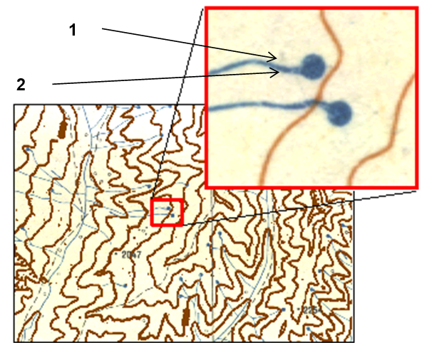
The preview area position in the image
4. When satisfied with the binarization results, repeat the procedure described above.
As a result of binarization a new layer named “Rivers” is CREATED, where the monochrome image MAP is placed.
5. Close the Binarization dialog box by clicking the Close button.
Save the image from the “Rivers” layer to a separate file.
1. Open the Images dialog box.
Choose Images from the Tools menu or click  on the Properties toolbar.
2. Choose Map(2) from the list of images.
3. Click the Save or Save as button.
For information on the Images dialog box see page Managing Images .
Post your comment on this topic.