
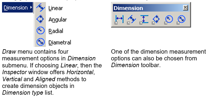
Dimensions
Dimensions are the objects that represent distances, angles, diameters and radiuses. A dimension object usually consists of dimension and extension lines, text and arrowheads.
The dimension object is created using current settings shown in Inspector window. Using grips some of the properties of the dimension object can be edited.
To create linear dimension
1. Select Linear from Draw > Dimension submenu.
2. Select Horizontal, Vertical and Aligned from Dimension type list in Inspector window. Set other options in Inspector window if necessary.
- or –
Press one of the three buttons  in the left of Dimension toolbar.
3. Click on end points of measured object. Watch the dashed contours of dimension text.
4. Move the mouse pointer until the desired position for the dimension text is reached and click again.
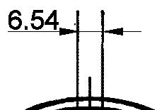

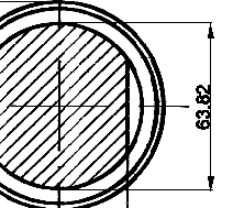
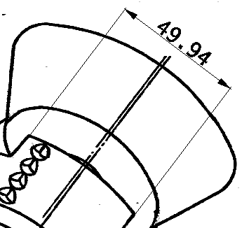
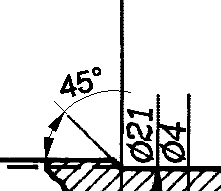
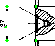
Distance dimensions examples
If the vector line is already selected, then there is no need to specify the dimension object. Choose Horizontal, Vertical and Aligned from Dimension type list in Inspector window and click to specify the dimension object position.
To create angular dimension
1. Select Angular  from Draw > Dimension submenu. Set options in Inspector window if necessary.
2. Specify the angle by three mouse clicks: first for angle vertex, others for directions. Watch the dashed contours of dimension text.
If the arc is already selected, then there is no need to specify the dimension of the object. Click once to specify the dimension.
3. Move the mouse pointer until the desired position of the dimension text is reached and click again. Note that if the mouse pointer is too close to the angle vertex and the dimension text does not fit in, then it is placed outside the measured sector. If the mouse pointer crosses the inner side of angle, then the outer angle is measured and vice versa.
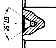
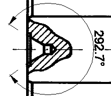
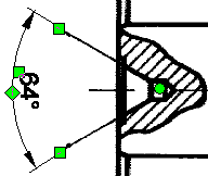
Angular dimensions examples
To create radial or diametral dimension
1. Select Radial  or Diametral
  from Draw > Dimension submenu. Set options in Inspector window if necessary.
2. Click on the centre and on a point on the circle (both for radius and diameter). Watch the dashed contours of dimension text.
If the circle or arc is already selected, then there is no need to specify the dimension object. Click once to specify the dimension.
3. Move the mouse pointer until the desired position of the dimension text is reached and click again. Note that the text that does not fit into the circle is placed outside.
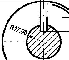
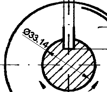
Radius and diameter dimensions examples
Editing dimension objects
The dimension object can be edited using grips and changing properties in the Inspector window.
To edit dimension object using grips
1. Select the dimension object. The grips appear. Square and diamond-shaped grips allow the dimension lines to be edited. The position of text can be changed by moving the grip next to it and also the vertex of the angle by moving the round grip of the angular or circular dimension objects.
The examples of dimension objects with grips
| Line Type | |
|---|---|
| Scale Width Type |
Sets line properties. |
| Start Marker End Marker Start and End Marker Scale |
Defines the shape and scale of makers at the ends of dimension lines. |
| Text Style | |
| Style | Select text style. |
| Font Height Width Factor Oblique |
Text properties. |
| Dimension Style | |
| Text Color | Sets color for text of dimension object. |
| Text Orientation | Text can Split Dimension Line or can be placed Above Dimension Line. |
| Inside Text Orientation | Defines orientation of the dimension text when it is situated inside extension lines. Text can have Horizontal or Parallel Dimension Line orientation. |
| Outside Text Orientation | Defines orientation of the dimension text when it is situated outside extension lines. Text can have Horizontal or Parallel Dimension Line orientation. |
| Text Precision | Defines the number of digits after decimal. The text precision value can be set to the Default value, which means that the text precision will be inherited from the current coordinate system precision. |
| Number Decimal Symbol | Specifies a symbol between integral and fractional part of dimension value (period, comma or space). |
| Text Gap | Defines the gap when text splits dimension line. |
| Text Offset | Defines how far text is shown above a dimension line. |
| Extend Line Break Length | Extension lines begin next to measured object. |
| Extend Line Over Distance | Extension lines end further than dimension line. |
| Dimension Lines | Shows dimension lines of dimension object: None, First, Second, Both. |
| Extension Lines | Shows extension lines of dimension object: None, First, Second, Both. |
| Markers Position | Defines the position of markers related to extension lines. |
| Markers Leadering | The length of dimension lines when Markers Position is set to Outside Extension Lines. (note that there are two Outside options) |
| Text Position | Text can be placed anywhere. There are several predefined positions (inside or outside dimension lines) and also the User Defined option, which can be used to precisely set the text position. The On Shelf option draws a connecting line between text and the dimension line. |
| Number Scale | Scales (increases or decreases) value of dimension object. (Suitable if the drawing isn’t at a scale of 1:1). |
| Scale Overall | Sets scale of displaying graphic elements (text, arrows) of dimension object on the screen. |
| Brackets | Encloses dimension text in brackets of specified shape: [Square], (Round), (Braces) , , None. |
| Dimension | |
| Style | Sets dimension style for dimension object. |
| Orientation | This parameter is available only for linear dimension objects and specifies orientation (type) of linear dimension object in the drawing: Aligned, Horizontal,. Vertical. |
Text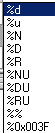 |
Contains text and special symbols that are interpreted when creating and editing the dimension object in the document Special symbols are the following: %N for linear dimensions, %R for radial, %D for diametric and %NU for radial. They are inserted automatically into the Text field when choosing dimension type. They can be combined with other text symbols, for example, the string “This line %N cm” in Text field becomes “This line 12 cm”, “This line 15 cm”, etc in the document, depending of measured object’s length. |
| Underline Text | Specifies additional text under dimension line. |
| Geometry | |
| Centre Radius First Second |
Precise coordinates of dimension object components. |
| Shift Angle | The dimension object is skewed (if applicable). |
To explode a dimension object
1. Select a dimension object.
2. Choose Explode form Modify menu.
The dimension object is exploded to separate lines and text.
Dimension styles
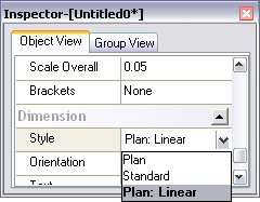
Dimension objects inherit values of their parameters from dimension styles. A dimension style for a dimension objects defines in the Style item of the Dimension section in the Inspector dialog.
If parameters of dimension style are change, the parameters of all dimension objects using this style are also change.
The Dimension Styles dialog uses for creating and editing dimension styles in the program.
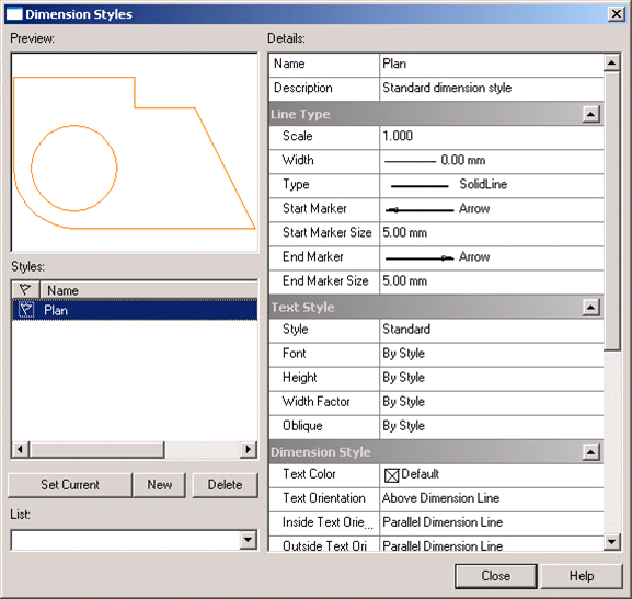
The preview window displays dimension objects, which edited dimension style is applied to.
To make a style current
New dimension objects are created on a base of a current dimension style. A dimension style can be made current by selecting it from the Style list and pressing the Set current button. Current dimension style is marked with a tag 
To create a new dimension style
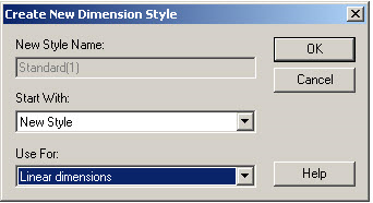
Press the New button to create a new dimension style. The Create New Dimension Style dialog will appear.
1. Enter a name of a new style.
2. From the dropdown Start With list specify a base style to create a new style. A new style will inherit the values of base style parameters.
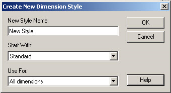
3. In the Use For field choose All dimensions.
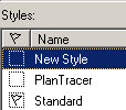
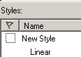
4. Press OK. A new style will be displayed in the list of styles.
Substyles of dimension styles
A dimension style can includes substyles for the certain dimension type:
• linear dimensions;
• angular dimensions;
• radius dimensions;
• diameter dimensions.
For example, if the ISO-25 style is created and contain a substyle for linear dimensions – Linear, then any linear dimension object based on the ISO-25 style will inherite parameters from the Linear substyle. If a base style does not have a substyle, then settings of a base style are used.
To create a substyle
Press the New button to create a substyle. The Create New Dimension Style dialog will appear.
1. The program specifies a name of a substyle automatically. The name of a substyle will have a name of a base style and a dimension type for which the substyle is created. For example, New style: Linear. A style name in the top field of the dialog will be blocked.
2. In the Start With field specify the style which the substyle will be created for.
3. From the Use For dropdown list specify type of dimension objects which the substyle will be created for.
4. Press OK. Substyle will be displayed in the list of styles under the name of a base style.
To delete a dimension style
A dimension style can be deleted in case it is not set current or not appointed for one dimension object in the document. To delete dimension style select it from the list and press Delete button.
Post your comment on this topic.