
Creating a set of Calibration Pairs
Creating calibration pairs adds their definitions to the list of the Calibration dialog box.
To create calibration pairs:
1. Specify the known theoretical point coordinates (real points). There are two ways to do this – define a calibration grid or add them one by one. Both methods may be used simultaneously. Upon creation, each calibration pair has the same measured and real point coordinates.
2. Specify the appropriate measured points for all real points by picking them on the image or entering the point coordinates from the keyboard.
Defining Calibration Grid
A calibration grid is helpful when calibrating images covered with the raster grid with nodes that must have known coordinates. Such images are, for example, scanned images of maps or geodetic plans.
Defining a calibration grid creates a set of calibration pairs placed in the nodes of a rectangular grid. These calibration pairs have the Grid type.
The position of grid nodes is determined by the origin, angle, cell size and the number of cells in the vertical and horizontal directions.
There can only be one grid defined on the image. Redefining a calibration grid removes all calibration pairs of the present grid from the image.
To define a calibration grid
1. Open the Calibration dialog box.
2. Click the  button in the Calibration dialog box.
The Calibration Grid dialog box appears:
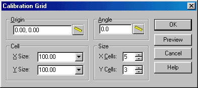
Calibration Grid dialog box
3. Specify the grid origin.
Enter its coordinates into Origin, or press the Measure button and click the origin location on the image.
The grid origin is assumed to be in the lower-left corner, and the grid is generated along the positive direction of the X and Y axis. To set a different corner and grid direction, set negative values in Size and Cell boxes.
4. Specify X Size and Y Size of the grid cell.
If it is necessary, then add grid columns in the negative direction of the X or Y axis by specifying a negative value for the X or Y size.
5. Specify numbers of grid cells along the X and Y axis using X Cell and Y Cell, accordingly.
6. To prevent mistakes, choose the Preview button to view the grid defined. Correct any mistakes if necessary.
7. Choose OK to create calibration grid and return to the Calibrate dialog box.
8. It is possible to construct a rectangular grid rotated by the defined angle. Otherwise, the grid rows and columns will be orthogonal to the X and Y axis.
Adding calibration pairs one by one
This method creates calibration pairs one by one. The created pairs may be of the Control, Check, or Unused type. The procedure is designed so that pairs can be created by indicating only the real point coordinates. The measured point coordinates can be defined later.
To add calibration pairs one by one
1. Open the Calibration dialog box.
2. From the cursor menu, choose Add or click the  button in the Calibration dialog box.
The following dialog box appears:
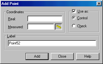
Add Point dialog box
3. Type the real point coordinates in Real.
4. Type the name for the pair in Label. Otherwise the default name of this pair is “PointNN”.
5. Type the measured points’ coordinates in Measured or pick the measured point coordinates in the screen by  button. Otherwise their coordinates will be equal to the real ones and can be modified later.
6. If necessary, then change the pair type in Use as from Control to Check or define the pair as Unused.
7. Press ENTER or choose Add to create the pair and con¬tinue the process.
8. Choose Close to return to the Calibration dialog box.
Post your comment on this topic.