
Vector auto correction
This procedure is intended for automatic correction of automatic and semi-automatic vectorization (tracing) results. It processes such vector objects as lines, arcs, and circles. After applying Auto correction it is also recommended to apply manual vector correction, if needed.
The results of Auto correction performance depends on the width of corrected vectors.
Autocorrection allows users:
• To restore the contact of lines with arcs and circles
• To “stick together” vector fragments in entire objects
• To delete vector objects if their size is smaller than specified. A line size is defined by its length, a circle size – by diameter, an arc size – by its largest projection onto the X and Y-axis.
• To align lines to regular directions (angle 0°, 30°, 45°, 60°, 90°, etc.) if their deviations from the specified values do not exceed the specified value.
To tune the Auto correction parameters
1. Choose Vector Correction Options from the Convert menu or press the  button on the Vector Correction toolbar.
The following dialog appears:
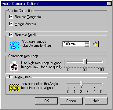
2. Turn on the Restore Tangents checkbox to restore the contact of lines with arcs.
Before applying Restore Tangents  Result of the Autocorrect command
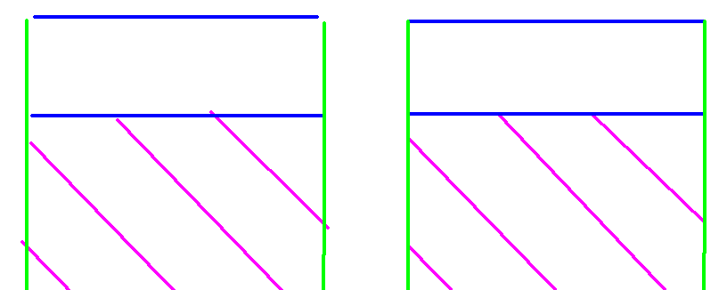
3. Turn on the Merge Vectors checkbox to “stick together” vector fragments into one object.
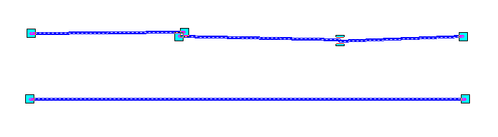
The lower figure shows the result of applying Merge for these three lines.
4. Turn on the Remove Small checkbox if automatic vectorization created some vector speckles – i.e. small vector objects that are not required.
The size of a vector speckle is defined in one of following ways: for a line – by its length, for a circle – by its diameter, for an arc – by its largest projection onto the X and Y-axis.
Specify the maximum size of speckle – all speckles with a size less or equal to this value will be removed.
Enter the maximum value for vector speckle in Remove Small. The measurement tool can also be used. Click on  and specify two points on the document, which define the size of a vector speckle.
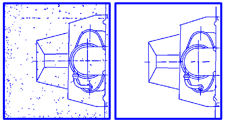
Before applying Remove Small Result of the Auto correct command
5. Enter the required value of Correction Accuracy in the corresponding box. Use high Accuracy for images of good quality, low for images of poor quality.
6. Turn on the Align Lines checkbox to use the feature of line alignment to regular angles.
Enter the deviation angle value in Align Lines – the command will align regular angles to those lines who’s deviations from the regular directions are equal to or smaller than the specified angle.
7. Choose Vector Autocorrect from the Convert menu or press the  button on the Vector Correction toolbar.
Example of auto correction of vectorization results
In this example the Autocorrection command expands and trims selected vectors by correcting their intersections.
Post your comment on this topic.