
Example of Image Calibration
This example shows the calibration of a colour image from the UTRECHT.TIF file of the SAMPLES subfolder of the program root folder.
Image loading
Choose Open from the File menu or click the Open button in the Main toolbar.
In the dialog box go to the SAMPLES folder and double-click the UTRECHT.TIF file name.
- or -
Select the UTRECHT.TIF file and press the Open button in the dialog box.
Note that this image sample has raster grid with a X-axis of 2 cells and an Y axis of 2 cells. The size of cells in this grid is known to be 32×32 mm, and in the original scanned image the grid cells are distorted. We assume that the whole image distortion corresponds to the grid distortion.
Use calibration procedure to eliminate distortion.
Open the Calibration dialog box
From the Image menu, choose Calibrate or on the Image toolbar, click the  button.
Creating a set of calibration pairs using calibration grid
1. Press  in the Calibration toolbar. The Calibration Grid dialog box appears.
2. Zoom to the image lower-left corner.
3. Enter the exact coordinates of the lower-left grid node to Origin the UCS is defined or press the Measure button  and click a point at the raster lower-left grid node, as shown in the figure below.
4. Specify X Size and Y Size of the grid cell.
Enter 32 to X Size and Y Size.
5. Specify numbers of grid cells along the X-axis and Y-axis entering 2 to X Cell and Y Cell, respectively.
6. Choose OK to create a calibration grid and return to the Calibrate dialog box.
A grid of calibration pairs is displayed.
The real and measured points of each calibration pair have the same coordinates. They represent the known position of raster grid nodes.
Define the measured points
1. Select the first calibration pair Grid (01,01) from the list in the Calibration dialog box. WiseImage highlights the selected point with grips.
2. Zoom to the selected pair by clicking the  button on the toolbar of the Calibration window. WiseImage pans the image so that the pair is shown in the centre of the screen. Use the standard
  button to view the required point more exactly.
3. Change the current measured point location.
Place the mouse cursor over the grip and click. Move the cursor and click again to specify its new location
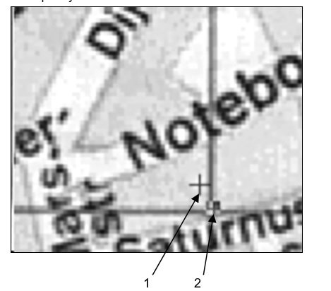
The figure above shows the real (1) and the measured (2) points positions. The real point of the calibration pair sets the known position of the raster grid node, and the measured point shows the position of the raster grid node on the original (distorted) image.
4. Go to the next calibration pair by pressing N or Tab hot key or press the  button in Calibration dialog box.
WiseImage pans the image so that the measured point of the next calibration pair is shown in the screen centre.
To go to the previous calibration pair, press P hot key or press the  button in the Calibration dialog box.
5. Repeat steps 3 and 4 for all calibration pairs to specify the measured point’s position.
Transformation method selection
As follows from the table on the Choosing Calibration Method, the Grid adaptive bilinear method is the most appropriate method to correct grid distortions.
From the Calibration Method list, select Grid adaptive bilinear.
- or -
Select Choose automatically from the same list.
To estimate the calibration transformation precision
Click the  button in the Calibration toolbar.
The program will find the calculated points’ coordinates –the points for the measured points of all calibration pairs to be moved to, and their position will be shown with yellow cross marks on the image. Also, the program calculates the distances between the calculated points and the real points of the calibration pairs in order to estimate the mean, maximal and minimal transformation errors. The values of these errors are shown in the boxes: Mean error, Min error and Max Error respectively.
In this case all these values are zeros. It means that all the raster grid nodes will get the required positions after calibration.
To start the calibration procedure
Start the image calibration procedure by clicking the Apply button in the Calibration toolbar.
Post your comment on this topic.