
Controlling Properties of Created Objects
Using the Separate tab of the Conversion Options dialog box, users can control the properties of created vector objects, calibrate the widths of obtained vector objects, place vector objects corresponding to raster lines from the specified ranges of width on new layers and/or assign various colours to created objects.
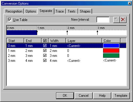
Separate Tab
| _.Parameter | Description |
|---|---|
| Use table | If this checkbox is on, then the program places objects on specified layer, the width of lines is set by the table values. |
New interval   |
Allows users to create and delete intervals of widths in the table. |
| Width table | Allows users to edit the intervals of objects widths, and to assign colour and layer of the line to an interval. |
Width table
To tune the width table correctly, define width interval boundaries so that the objects obtained after vectorization of raster lines with the same width fit in the same width interval.
The width table can contain any number of width intervals. Each interval is defined by two values – a lower and high width boundary which recognized objects must fall into the specified interval. Width, colour and layer are defined to each interval, and these properties are assigned to the objects that fall into each interval according to its width.
Real raster lines widths vary around the true value. For example, if vectorizing raster lines with a width of 0.25 mm, objects with widths from 0.18 to 0.33 mm can be obtained, and lines with width of 0.5 mm turning into vector objects with width from 0.35 up to 0.7 mm. Users can set widths, colours and layers for the created intervals and check out the operation of vectorization or tracing tools with the use of the obtained width table (with the Use the table checkbox on). All intervals are set within a width range from zero to the value of the parameter Max Width specified in the Options tab of the Conversion Options dialog box.

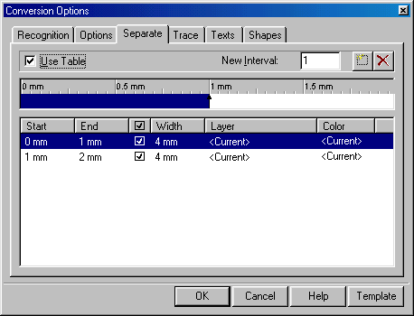
To create a new interval in the width table
 Enter a value for the upper boundary of the width interval into New interval, press the Create interval button.
Users can also create an interval by clicking on the appropriate position in the width table ruler.

An arrow appears on the ruler indicating the upper boundary of the created interval. The existing interval is divided into two intervals. The properties of a new interval are inherited from the existing one.
Users can modify boundaries of all intervals except the highest and the lowest, which always have the values Max Width and 0 respectively. Changing the boundary of one interval affects boundary of an adjacent interval. If the upper value of a boundary is set to be greater than the upper value of an adjacent interval, then this interval will be deleted. Intervals can also be deleted using the Delete button.
Boundaries and delete intervals can be changed by moving the arrow symbols on the ruler.

To change the interval boundary
Click in the width table on the line corresponding to the required interval, click on the box in the Start or End columns in the highlighted line and change the value of upper or lower interval boundary.
or
Drag the corresponding arrow symbol on width ruler.
All intervals except the default one can be deleted.
To delete an interval from the width table
Select an interval in the width ruler or from the list, and then click  – Delete interval button.
or
Indicate the left (lower) interval boundary on the width ruler and drag it to the left across the boundary of the nearest interval – the adjacent interval will be merged, and the created interval will obtain a new bottom boundary. If it is dragged across the right (upper) interval boundary, then the interval will also be deleted.
Modifying interval properties
The following properties are set to each interval: source width boundaries, width of created lines, colour and layer. These properties are assigned to objects with widths within this interval.
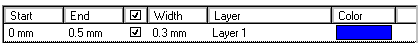
The width table line: Start, End, checkbox, width, layer and colour.
To keep widths unmodified
The value of Width will be assigned to all vector objects with width within the specified interval if the checkbox of width assignment is on.
To avoid the lines within the interval being rounded to a predefined width, specified in the Width box, remove the checkmark in the corresponding row of table.
To assign width to an interval
Click on a width table line appropriate to the required interval, click on the Width column and enter width value.
To assign layer to an interval
Users can assign any name of layer to an interval or select the Current value. All vector objects, with width falling into the specified interval, will be created on the specified layer. If there is no layer with the specified name, then such a layer will be created during tracing (vectorization). On choosing Current, the objects will be created on the current layer.
Click on the width table line corresponding to the required interval; click the Layer column in the list. Select existing layer from the list or enter a name of a new layer, which will be created during vectorization.
To assign colour to an interval
Click on the width table line corresponding to the required interval; click the Colour column in the list. Select colour from the list or specify in the dialog box opening by clicking Other. Users can assign any colour to an interval, including the values Current, By Layer and By Block. All vector objects with widths within the specified interval will inherit the specified colour. If Current is chosen, then the objects of the specified interval will be created with the current colour.
Saving Width Table Settings
Width table settings can be saved in a template file for further use (along with other settings of Conversion Options dialog).
To save width table settings
1. Click on the Template button; choose Save from the list.
2. A dialog box for saving the template file will open.
3. Specify the file name and click OK. By default the file will be saved to the Recognition parameters subfolder of the WiseImage root folder.
To load width table settings
1. Click on the Template button and choose Load from the list.
2. A dialog box for loading template files will open.
3. Choose the required file and click OK.
Post your comment on this topic.