
Tracing polylines (Line follow)
This method allows the user to trace arbitrary raster lines with an approximating vector polyline. When tracing, specify a point on the raster line, and the program automatically tracks this line (direction of the line follow can be specified) up to the nearest node or intersection point, and creates an approximating vector polyline that consists of line segments. The node of a raster line is either its end point, or a point where the raster line crosses the other raster object. During a single tracing session between two mouse clicks (it is called tracing step) you trace a set of polyline segments. One tracing step can take an arbitrary number of segments, depending on the line complexity and trace settings.
After each tracing step, choose the direction for further tracing, or complete the procedure. If the traced polyline crosses itself, then the tracing will be automatically completed. The direction can be chosen by specifying a point on the next adjacent part of the raster line. There are options to redo the latest tracing step (except the first one), and the last polyline segment within a step.
The autodetection mode of tracing extension direction can be turned on (see Trace tab in Conversion Options dialog). In this mode the program offers a possible direction, showing a special marker on the part that is selected as an extension. another direction can be selected during the given period (by default the waiting mode is off – waiting pause is 0), or accept the automatic trace extension. If no direction is chosen, then after the waiting period expires, the program will automatically continue tracing in the selected direction.
When tracing raster polylines the orthogonalization mode can also be used. It allows users to align obtained line segments by the base angle.
More detailed information on polyline orthogonalization mode is provided in section Tuning Tracing.
Tracing raster polylines is also influenced by the parameters Max Width, Max Break and Approximation Accuracy which specify maximum width of a raster line, value of ignored break and accuracy of a raster line approximation.
More detailed information on these parameters is provided in Tuning Tracing.
When tracing polylines several options are available; these are found in the cursor menu when working in Line Following mode.
|_. Option |_. Description |
| Cancel | Cancels the current tracing session; all the polyline created is deleted. After the end of tracing users can undo the result applying Undo command from Edit menu. Users can also cancel the tracing session by pressing ESC. |
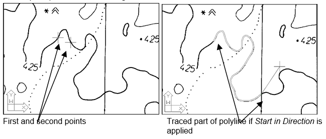
| Start in Direction | Can be used just after activation of Line Following method. If selected, then this option forces the program to treat the first two clicks on the raster line being traced as the direction of the polyline to be created. |
| End | Ends the tracing; to trace more, activate the Line Following method again. |
| Back Step | Cancels the last tracing step. |
| Back Segment | Cancels the last polyline segment. |
| Force Segment | Enables a linear segment to polyline to be added without tracing. Several segments can be added with SHIFT pressed. |
| Change Direction | Inverts the tracing direction. |
| Pan to Centre | Zooms the image to show the last added polyline vertex in the screen centre. |
Now we will describe in details the procedure of polyline tracing without autodetection of tracing direction (the fragment of the map used in this example you can find on CS_MAP.TIF in SAMPLES subfolder).
To trace a polyline
1. Choose Line follow from Convert menu or press  button on Raster to Vector toolbar.
To have complete control over the tracing procedure and so that tracing results are clearly visible, be sure to choose contrast Colour in the Inspector window for a polyline created. Also make sure that in the AutoDetect Direction checkbox in the Trace tab of Conversion Options dialog is off.
2. Pick any point on the raster line.
Starting from this point, WiseImage traces the selected raster line in both directions until in meets the two nearest intersections or breaks.
The program automatically determines the tracing direction. The rubber line is stretched out from the mouse cursor indicating the current tracing direction.
An example of starting the tracing procedure by picking of one point (used by default) is shown in the figure below.
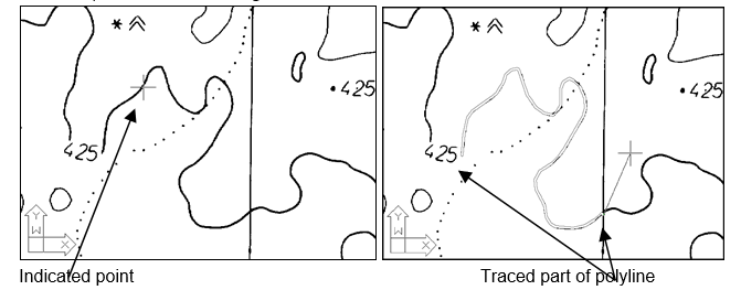
Suppose that we need to trace in the opposite direction. To change the direction, press the right mouse button and choose Change Direction. Then specify a point on the raster line. When specifying a tracing direction in which to start, WiseImage starts tracing the raster line at the first of the indicated points and proceeds to the node nearest to the second indicated point. An example of tracing start with the tracing direction indicated (Change Direction option) is shown in the figure below.
3. To trace the next part of the raster line in the current direction, indicate a point on it. WiseImage traces a raster line up to the nearest node.
- or -
To change the tracing direction, select the Change Direction from the cursor menu and indicate any point on the traced polyline near the opposite vertex.
- or -
To create one linear polyline segment manually (without tracing); select the Force Segment option. Then indicate a point. The line section will link the indicated point with the last trace point.
This option allows you to eliminate breaks of a raster line, drawing a straight segment of the polyline.
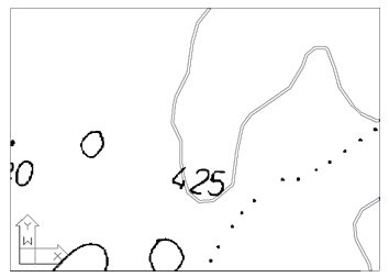
 The example shows an isoline on a raster map broken with text. We draw a rubberline over the gap.

 Specifying the raster line extension without using the Force Segment option results in one linear segment filling the gap.
 Use the Force Segment option to draw the missing parts, consisting of many linear segments, as the figure illustrates.
4. Repeat step 3 until tracing a raster line is complete.
If the results are not satisfactory, then use the Back Step and Back Segment options. The first option cancels all polyline segments obtained at the last tracing step, and the second option enables the polyline segments obtained within one step to be cancelled.. These options can be applied several times to cancel any number of steps or segments.
WiseImage automatically stops tracing a polyline, if the latest created polyline segment crosses any other segment of the same polyline, or if the latest segment vertex is located close to the first vertex of the same polyline. In the latter case a closed polyline is created, and tracing is completed.
5. To stop tracing press ENTER.
When tracing polylines with autodetection of direction, the program on reaching a node tries to determine the trace direction, and draws a marker on the suggested raster line extension (cross of the current colour).
Pressing SPACE accepts the tracing direction, suggested by the program. You can also select another tracing direction by specifying a point on the required part of the raster line. A choice of direction must be made in the given time period. This interval is set by the Pause parameter in the Trace tab of Conversion Options dialog.
If the program fails to determine a direction automatically, then a prompt to indicate a direction manually will appear, and once selected, tracing will continue operating in the automatic detection mode.
When tracing polylines, it may be useful to split the document window to two or four panes, setting different zoom values in them; both the entire picture and small details can be viewed in the window. The Split commands are described in details on Zoom, Pan and Named views.
Several images can be grouped using the Group command from the Modify menu. The linefollowing tool ”jumps” from the end of line on one image to its continuation on another one, creating a single polyline based on several raster sources. This “jump” can be implemented only if the images in the group have the same DPI value.
For information on grouping Groups.
If the image is clipped, then linefollowing stops at clipping boundary.
If monochrome images overlap each other, then tracing begins and continues on the image raster line of which was clicked first. The polyline is only traced on that image, ignoring visual intersections with raster objects on other images. If the overlapping images are grouped by Modify > Group command, then tracing is performed as if the images were merged. The polyline is traced considering all the visible intersections.
Post your comment on this topic.