
Forced Selection
There are 5 buttons that define forced methods of selection: Line, Circle, Arc, Floodfill, and Symbol.
There are also 5 “violet-styled” buttons in More Select toolbar that use the floodfilling selection method described in .
The Line, Arc, and Circle methods select raster entities of a specified type. These selection methods require drawing a reference rubber line of an appropriate type over a raster object to be selected. The program selects the specified raster object if it is recognized as a raster entity of the specified type.
These methods work in the similar way to the Object method (in Entity Recognition mode). Transforming and deleting raster entities selected with these methods do not break raster objects they cross, since intersections are preserved. The Approximation Accuracy, Max Width and Max Break parameters influence these methods. For description of these parameters see Tuning Selection.
Forced selection is also influenced by the Auto Extend Vectors mode, which is toggled in the Trace tab of Conversion Options dialog (see Tuning Tracing).
Unlike the Object method, Line, Arc, and Circle allow users to select a part of a raster entity, as well as considerably deformed entities. These methods only select raster lines.
While selecting with the Line or Arc method the endpoints (one or both) of reference rubber lines or rubber arcs can be picked outside the raster objects being selected – on their imaginary extension. In this case the raster object is selected up to its endpoints. If the reference rubber line endpoints lie on a raster object, then the program selects the part of the raster object underneath the reference rubber line.
To select a raster entity underneath the reference rubberline
From the Raster Select toolbar, click the appropriate button to the reference rubberline:  ,
,  , or
, or  :
:
| Line | Specify the endpoints of the reference rubber line. They can be either on a raster line or on its extension. |
| Arc | Specify three points of the reference rubber arc. The end points can be either on the arc or on its extension. |
| Circle | Specify two opposite points of a rubber circle over a raster circle. |
The reference rubber line is removed, and the raster data underneath is selected.
Raster Symbol Selection
The Symbol selection method allows selecting by picking raster objects, which have matching predefined templates.
The procedure of symbol sample defining is described in “Setting Up Symbol Recognizing Options” on Scanning of this guide.
To select a raster symbol
 |
1. Click the button on the Raster Select toolbar. 2. Pick a point on the raster symbol. |
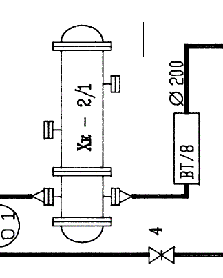
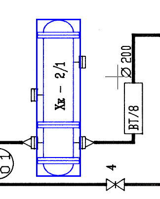
These figures illustrate raster symbol selection. Using this method the user can choose notation conventions in scanned electrical, hydraulic schematics, maps, and similar images.
Post your comment on this topic.