
Automatic Color Vectorization
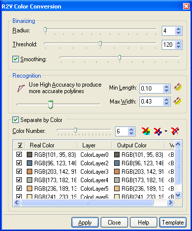
Color Conversion is intended for recognition of linear objects on color schematic raster images (plans, schemes, topographical maps). It combines such operations as binarization, vector color separation and color vectorization. . As a result, you get polylines broken in places of mutual crossings.
This command works on greyscale and colour images.
To start the Color Conversion command; choose Color Conversion Options from the Convert menu or click the  button on the Raster to Vector toolbar.
To tune the colour conversion parameters do following steps:
Step1
Adjust the binarization parameters (similarly to Adaptive Binarization):
Switch on the Hide Vectors button  of this dialog, switch off the Hide Raster button
  and the Hide Source Raster button
Move the Radius slider to its minimum position (equal to 4).
Gradually increase the Threshold value until the required objects appear.
Use the Smoothing filter if the objects have rough borders.
At the same time, closely positioned lines might conglutinate and small objects might disappear.
related buttons and controls:
 Hide Source Raster button
 |
Turns off the display of source raster image in the Color Conversion preview area. |
 Hide Vectors button |
Turns off the display of vector objects in the Color Conversion preview area. |
 Hide Raster button |
Turns off the display of raster information in the Color Conversion preview area. Click the arrow to the right of the button to change colour of binorized raster data. |
| Radius slider | Sets the radius value, which determines the depth (in pixel) of the filter effect on the colour area. Set it to the minimum position. |
| Threshold slider | Sets the threshold value of binarization. |
| Smoothing | Select this checkbox to smooth the image. The Smoothing slider controls the smooth level. Moving this slider right makes the smooth level higher while moving left makes it lower. |
Step2
Set the Recognition parameters: Max Width, Min Length and Accuracy.
These parameters are equal to those for monochrome images in the raster to vector Conversion Options dialog and the Raster Properties toolbar.
related buttons and controls:
| Min Length | Sets the minimum length of a raster fragment which should be recognized as a polyline in the vectorization process. - Specify the length of the shortest raster line. - In order to measure directly from the image, click the  button and draw a line along the smallest raster line. button and draw a line along the smallest raster line. |
| Max Width | Sets the maximum width of a raster linear object which should be recognized as a polyline. - Specify the value of this parameter slightly greater than the maximum width of the raster line to vectorize. - If the program does not vectorize raster segments, then increase the value of this parameter. If the program does not approximate flooded raster areas by boundary objects, then reduce the value of this parameter. - In order to measure directly from the image click the  button and draw a perpendicular line to the widest raster line you want to recognize. button and draw a perpendicular line to the widest raster line you want to recognize. |
| Accuracy slider | Sets the accuracy of raster lines approximated by vector objects. If the quality of the raster image is poor, then reduce the parameter value so that the function will be able to recognize raster objects with significant form distortions. |
Step3
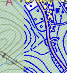
Switch off the Separate by Color checkbox and define a preview area so that all the objects of all the colours present in the raster image can be seen.
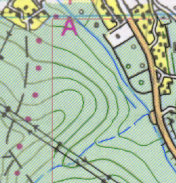
Visually check the quality of the recognized objects, their colour and degree of conformity to the raster image. Re-customise parameters if necessary.
To see lines of different colours on separate layers, switch on the Separate by Colour checkbox.
Set the Colour Number value (usually 1-2 colours more than the real number). The program automatically defines the table of colours and casts the colour of an object to the nearest one. By switching on/off the Export to Layer checkbox located at the beginning of every colour table string, all objects of this colour can be checked visually.
After defining the correct number of colours it is possible to define another target colour and a layer for each real colour.
If there is no need to export a line of a certain color, then switch off the Export checkbox at the beginning of this string.
related buttons and controls:
| Colour Number slider | The Separate by Color section tries to automatically reduce the colours of all raster lines to a fixed number (Real Color column). Only the number of the colors to reduce to need to be set (usually, 1-2 colours more than the real number). Because the color of a raster line can slightly vary from its beginning to its end after vectorizing vector polylines of two different colours are produced whereas the actual color is the same. |
| Check box column | Turn it off to exclude polylines of a specified color from the vectorization process. |
| Real Colour column | A fixed number of colors that is generated automatically by the Color Conversion tool on the basis of the Color Number value. |
| Layer column | Set a layer for the vector set of a specified color. |
| Output Colour column | Specify a color for the vectorized polyline set. |
Step4
Click the Apply button to start vectorization or save the parameters to a file for further use.
Vectorization can also be launched with current settings through the Raster2Vector command (chose the Raster2Vector from Convert menu or click the  button on the Raster to Vector toolbar).
related buttons and controls:
| Apply button | Launches the color conversion process. |
| Close button | Closes the R2V Color Conversion dialog keeping all its parameters. |
| Template button | Allows users to save current settings to a file for future use. |
Post your comment on this topic.