nanoCAD Mechanica is an advanced application developed for mechanical engineers, designers and drafters, giving them with prospects in the field of automation of design and construction work in numerous areas of the manufacturing industry. nanoCAD Mechanica is a standalone 2D drafting and design software with a large library of standard parts and tools designed to help program design tasks and for mechanical drawings creation. When designers form mechanical designs using nanoCAD Mechanica, they evade boring routines and monotonous manual tasks usually required to get the job done. nanoCAD Mechanica helps designers accelerate design, reduce development time and provide their products to market – easily!
Increase Your Productivity With nanoCAD Mechanica!
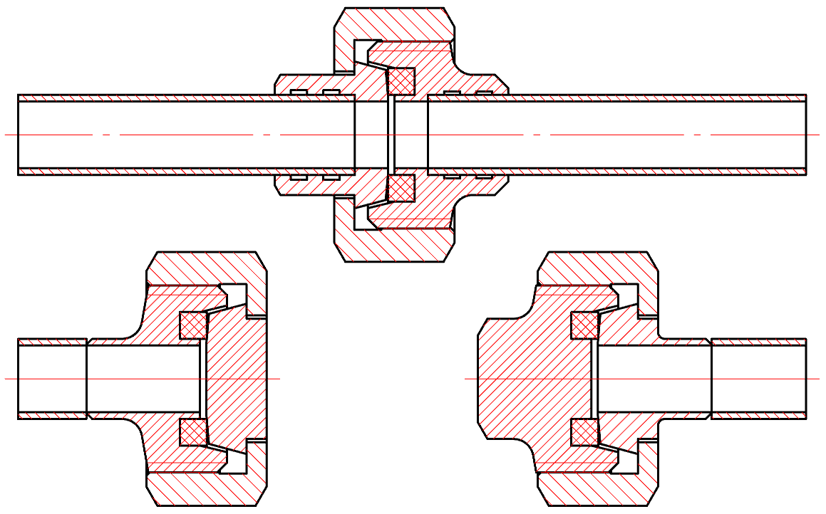
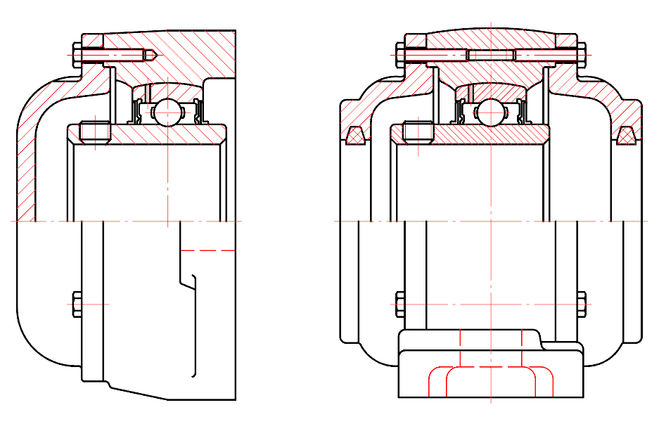
Easily save time with a complete user-expandable library of mechanical parts (gearboxes, shafts, pneumatics and hydraulics pipes etc.) with fixed parametric links supporting international drafting standards (ISO, DIN and others).
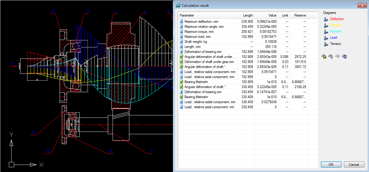
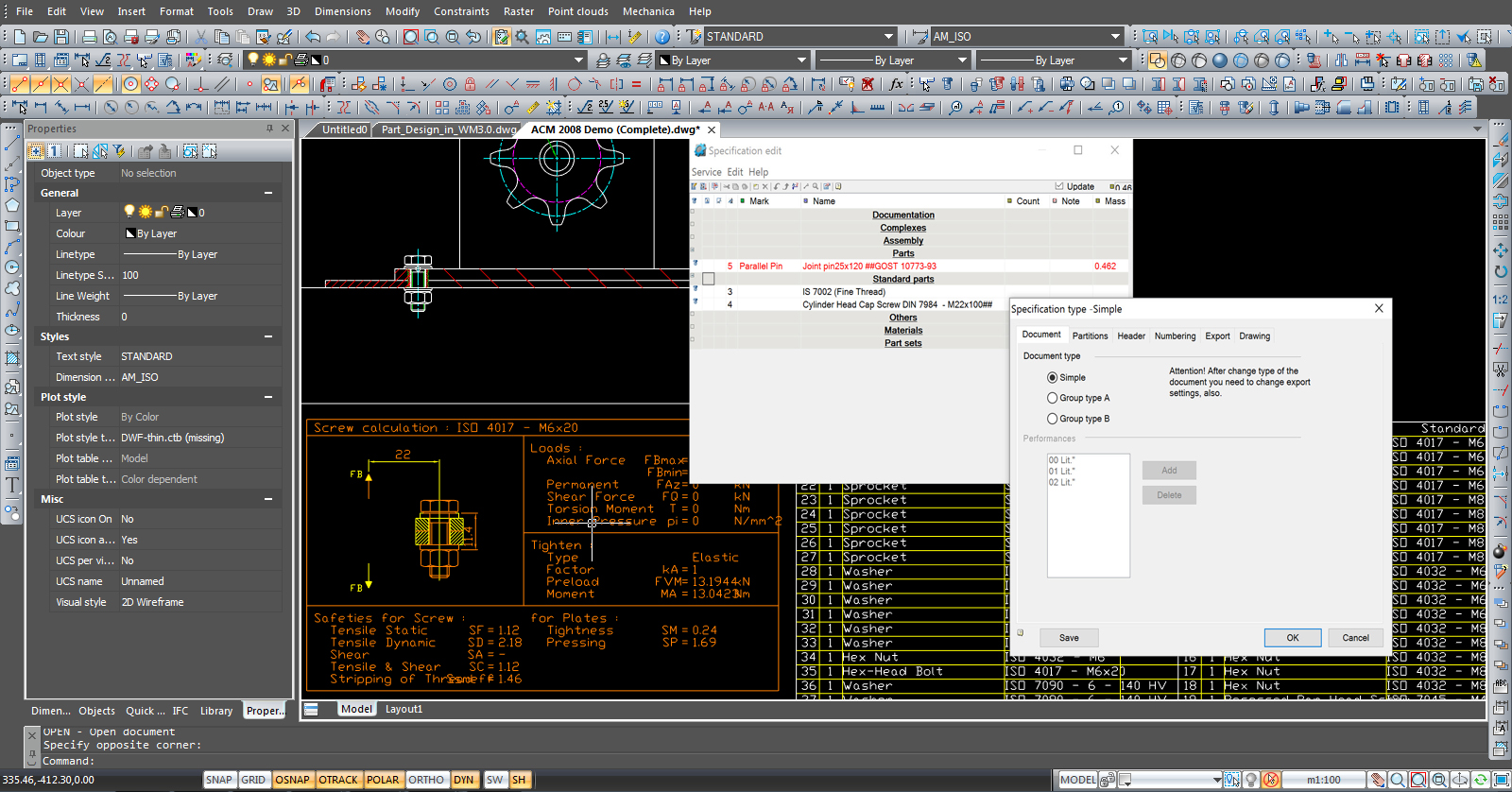
nanoCAD Mechanica offers a commanding tool that automatically alternates all linked parts if you change one of them; this advances the quality of the mechanical drafting development. nanoCAD Mechanica delivers automatic connection of fittings with pipeline elements. Element size and placement coordinates are easily detected. The software allows you to make Fastening and Rivet connections with ease. Moreover, nanoCAD Mechanica allows you to achieve all engineering calculations easily. Also, you can find a number of drawing design symbols (leaders, surface textures, tolerances, dimensions, views, sections, welding and etc.) for everyday tasks.
Furthermore, drafting tools consist of automated formation of Part list, with a flexible and natural control of structure and content.
The core of the system
Functional nanoCAD Mechanica include a typical set of design tools, including:
nanoCAD has a well-organized, and easy to learn, classic-style CAD user interface. It provides a command set and UI elements look that will be well acquainted and comfortable to users of many other compatible CAD applications. The drawing space, command line, and position of the menu items and icons on the toolbars are easily identifiable. Any person with CAD knowledge will feel at home using this powerful CAD software, right from the start.
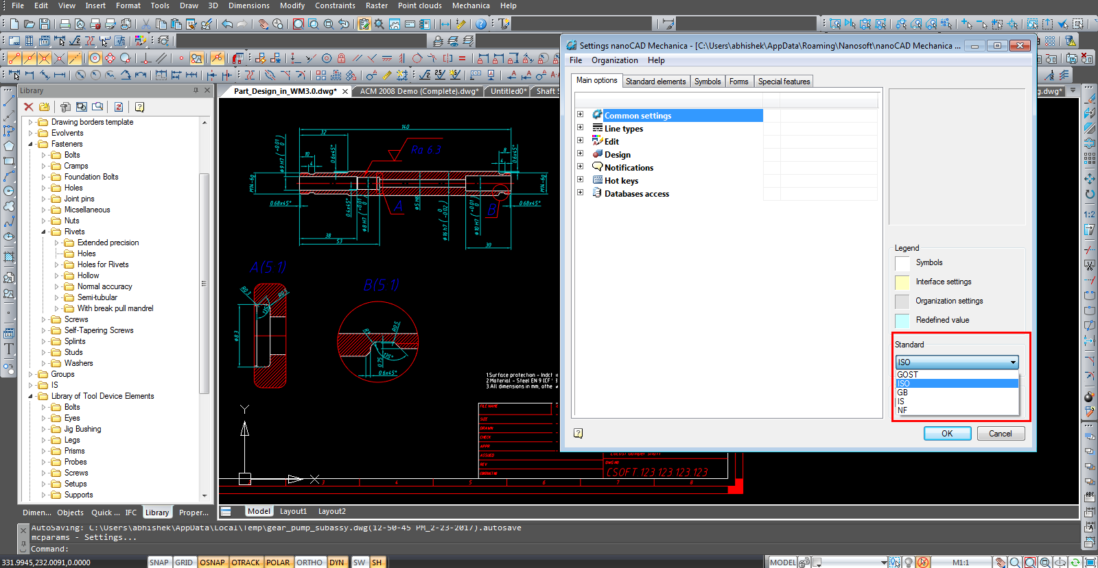
nanoCAD provides direct *.dwg support. It uses the industry-standard DWG (*.dwg) file format natively. The most commonly used CAD design format. This means that not only it offers usability while moving from a different CAD tool to nanoCAD, the opposite is also true. Drawings created or edited in nanoCAD can be used by almost any other popular CAD system, without conversion or data loss. Be rest assured you will not lose file data due to software or hardware failures thanks to this 3D application’s auto saving and backup functions.
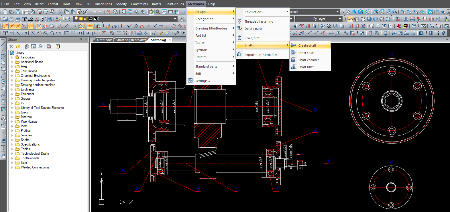
nanoCAD includes a multiple set of appropriate CAD tools to create & edit almost all kinds of 2D primitives. There are often multiple drawing methods available for creating most of geometric elements.
nanoCAD has a powerful Excel-style table editor, with an extensive set of capabilities. It has distinctive CAD design attributes and very beneficial for creating tables with macros in their cell.)
The 3D CAD application scripting engine allows normal users to automate everyday monotonous tasks. Users can write macros using Visual Basic Script, Java Script or any other scripting language supported by Microsoft Windows and built-in LISP.
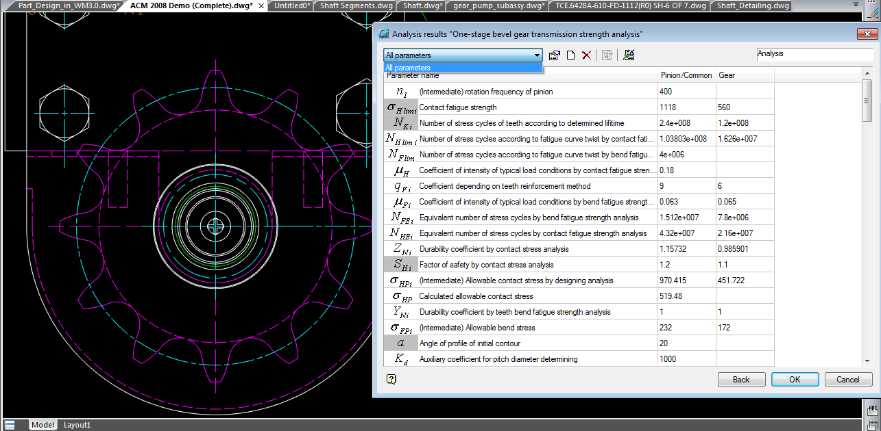
nanoCAD’ s plot settings dialog allow you to set various plot areas, and create multi-page plots. This can be exclusively useful for printing large drawings on printers with smaller output format. It also supports outputting drawings to single or multi-sheet plot files.
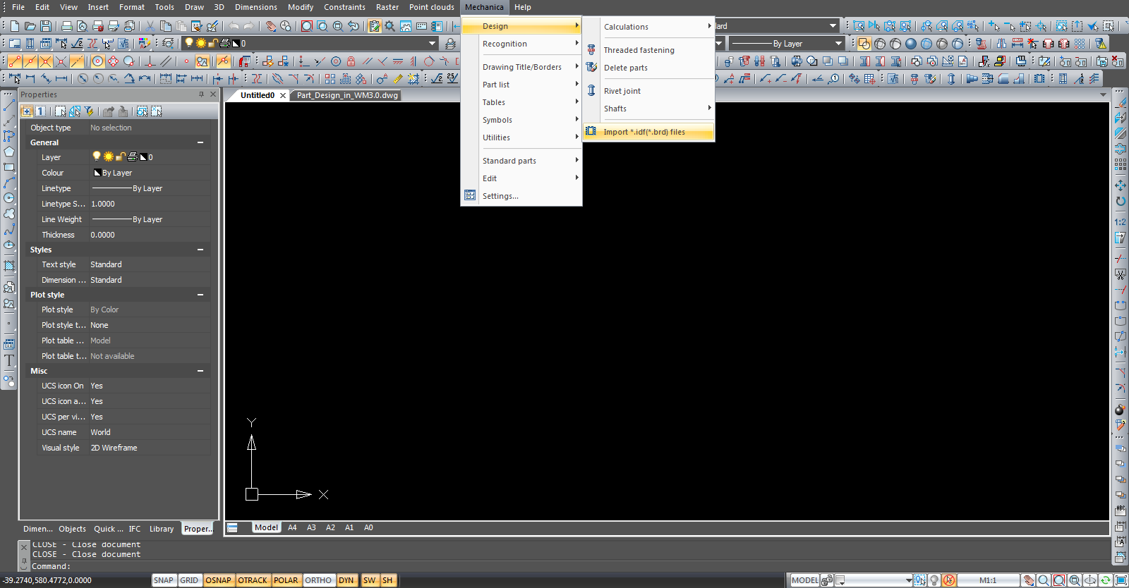
Dynamic Input supplies a command line interface. Using dimensional objects users can display of dynamic dimensions and edits their values . It also delivers for user entry to input like the length of a line or the radius of a circle.
Tool palettes deliver great prospects for fast and easy access to your preferred commands and blocks.
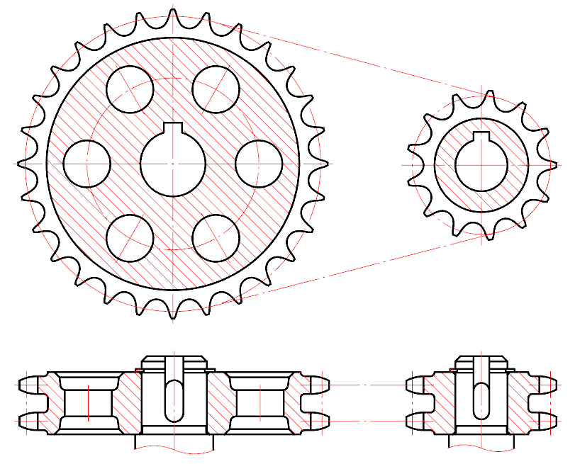
The base of standard elements has been considerably extended with standard products and structural elements for belt and chain drives. The new version includes such elements as:
single tooth image; detailed image.
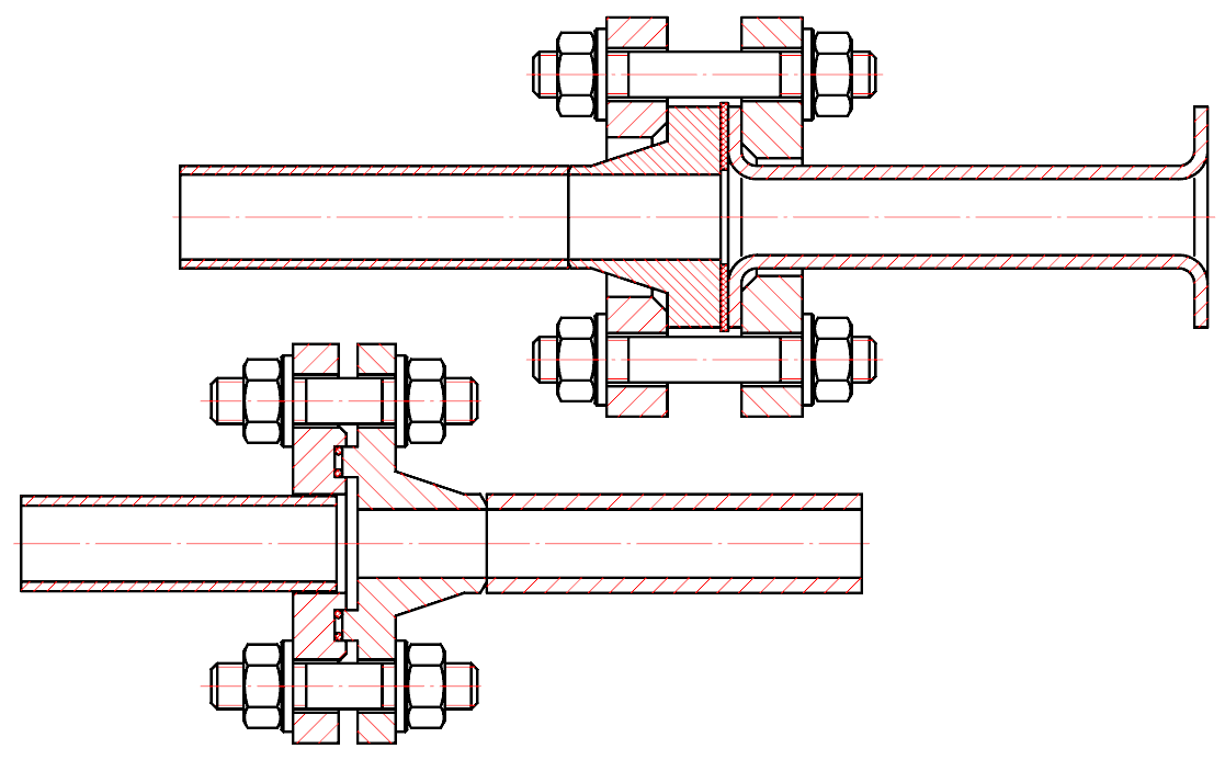
The following standard items have been added to the flange catalog:
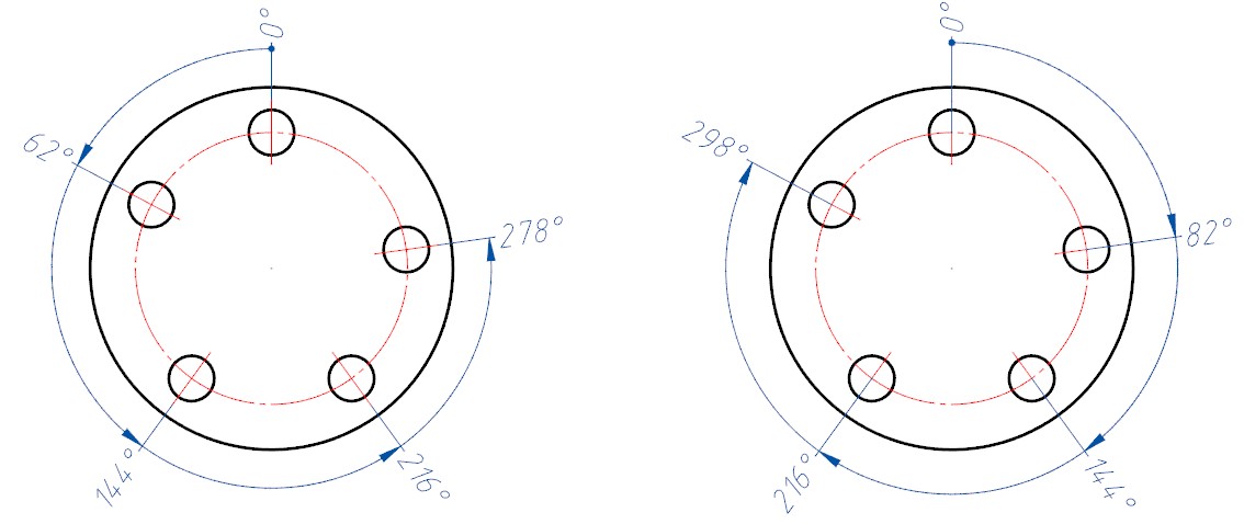
The following standard items have been added to the flange catalog:
