PlanTracer is a simple-to-use application that can perform complex automation from real -estate inventory using legacy floor-plans of any building. Plans are the foundation of PlanTracer and possess several unique features – plans consist not only of graphic primitives such as lines, arches and geometrical shapes, as found in other CAD -systems, but also of PT-objects - walls, stairs, windows, doors, rooms, furniture, fixtures etc. These objects are converted and can be edited as one unit. Thus, a floor plan created using PlanTracer represents a set of PT-objects that can be given as inventory related to the real -estate. Besides PlanTracer core functionality of making it possible to take an original CAD -drawing of a building, or use a plan from paper; the principle of transforming the initial plan into a plan consisting of PT objects is that PlanTracer (using preset Search patterns of objects) searches for similar imagery on the initial plans, and, having recognized these, inserts them into the corresponding place of the corresponding Graphical image.
PlanTracer 18 compatible with AutoCAD 2017-2018 and supports AutoCAD x86 & x64.
PlanTracer delivers advanced tools for floor plan drawing and editing in addition to AutoCAD's tools. Its unique toolset also includes automatic and semi-automatic conversion of input such as 2D CAD drawings or raster floor and building plans into intelligent models. PlanTracer provides an open programming interface for easy integration with Facilities Management applications, databases and MS Office. A Facilities Management solution can access all objects in a PlanTracer floor plan model.
Three modes of floor plan creation are available:
All modes allow the use of precise drawing tools: object snapping, relative object insertion, dynamic dimensioning, and more.
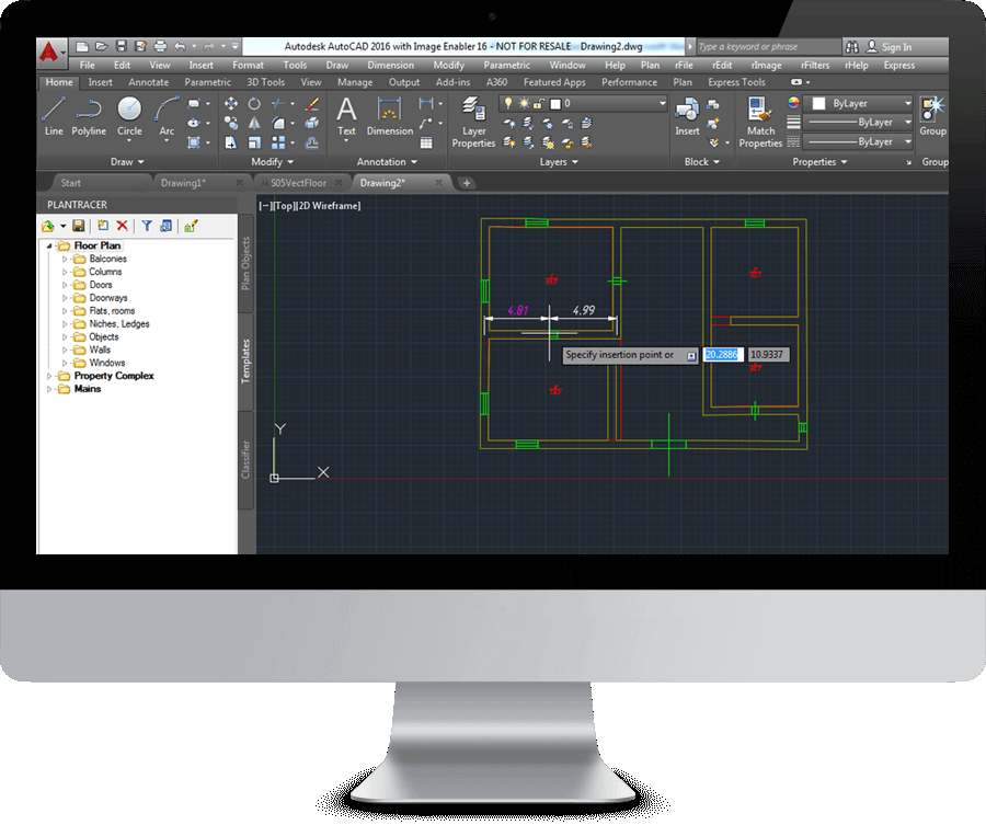
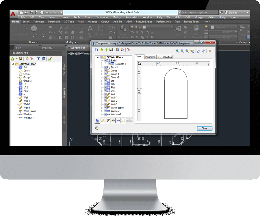
All building elements in a parametric floor plan model are stored using templates in the Object Library. This library is user managed. Libraries are loaded and unloaded as required. Library objects can be created directly from AutoCAD blocks or sets of entities.
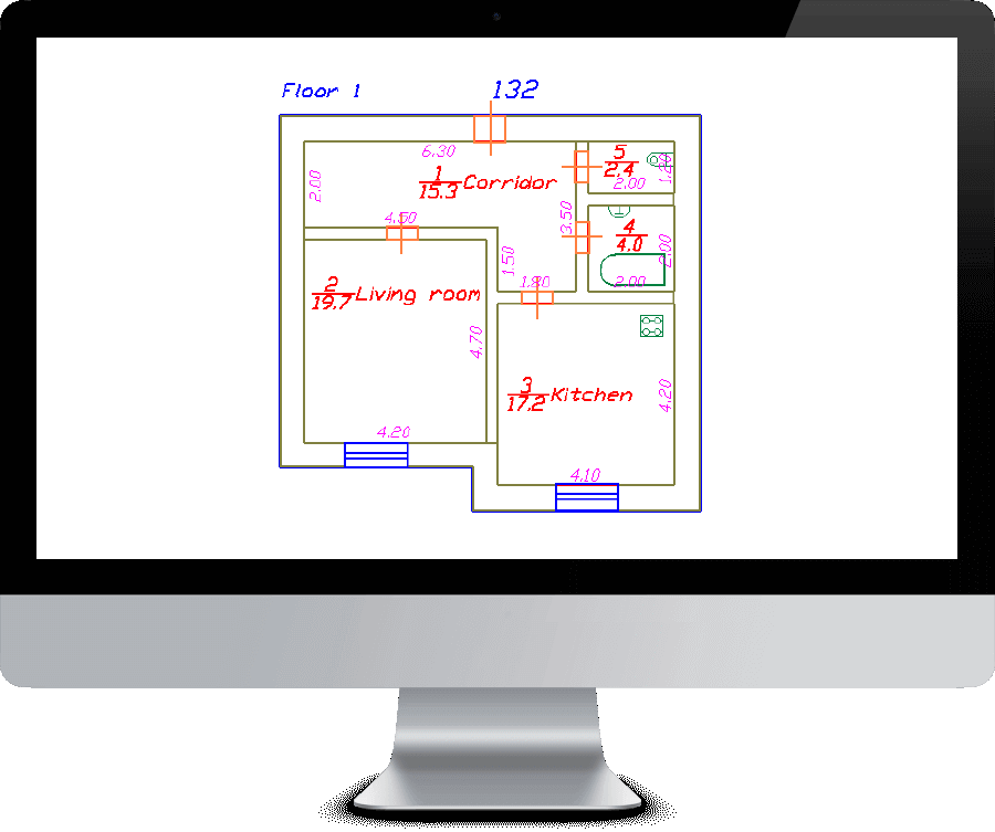
FM users usually create contours for rooms according to on-site measurements. The user obtains exact floor space areas with corresponding formulas to calculate them.
• Automatic conversion of original floor plans made from room measuring to parametric model (parametric mode)
• Traditional floor plan drawing using parametric library objects (library mode)
• Floor plan creation from measured outer and inner contours of the building (contour mode)
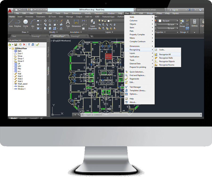
To create the floor plan model is only part of the job. It is also imperative to keep it up-to-date. The user is able to use dedicated walls correction commands, such as adjoining, trimming, extending, line-to-curved wall conversion, etc.
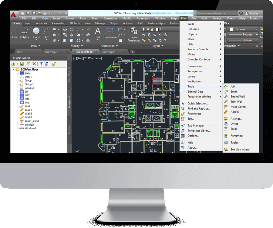
A Facilities Management solution can integrate PlanTracer using the built in COM API to access the floor plan model. It provides direct link to external databases, MS Office applications (e.g. Excel) and other FM applications. In addition to direct link via programming interface PlanTracer facilitate data exchange via IFC and XML files in addition to AutoCAD DWG files.
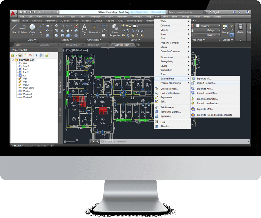
It is impossible to create one FM classifier fit for all users. PlanTracer has an application-independent data structure that allows users to maintain proper facility standards. The multi-level classifier structure provides users with the ability to create a proprietary system of definitions.